The question is if we talk about achievable preamp noise, with the cartridge, and the real-life noise with the vinyl record, that dominates, if the preamp is at least reasonably designed.
You might be surprised, but I have a different reason why to vote for the JFET input. The reason is much higher RFI immunity and immunity to input rectification, of the JFETs. JFETs are much better in this regard than BJTs and BJT input opamps. I also want for my phono preamp to be absolutely hum an buzz free, when connected into the audio chain. Real life whole audio chain is the target, not the single component theoretical parameters.
You might be surprised, but I have a different reason why to vote for the JFET input. The reason is much higher RFI immunity and immunity to input rectification, of the JFETs. JFETs are much better in this regard than BJTs and BJT input opamps. I also want for my phono preamp to be absolutely hum an buzz free, when connected into the audio chain. Real life whole audio chain is the target, not the single component theoretical parameters.
I still do not understand the fight for the lowest noise MM preamp, if the real life vinyl groove noise destroys all the possible achievements (the same applies to the so called active damping principle). The real life improvement is zero and I agree, we need to measure the real life situation, however it must include the vinyl source record, otherwise it is just another game toy. I have dozens to hundreds of measurements with real life vinyl records, including the measuring records.
That attitude just spoils the fun:
-Unless you do something really stupid, noise is bound to be less than the noise of the record, so there is no need to optimize noise
-Unless you do something really stupid, distortion will always be less than the distortion of a vinyl record, so there is no need to think about distortion
-Unless you do something really stupid, the RIAA conformity is bound to be better than the +/- 2 dB or so frequency response aberrations of the cartridge, so there is no need to design for good RIAA conformity
At least the RIAA amplifier noise can still be audible in between records, when you turn up the volume high enough.
I thought that there's at least 400pf in parallel with the cartridge and sometimes even a series resistor with the transistor base which makes kind of impossible for the bipolar input to rectify any RF...I asked for solid proof ...not sci-fi movies...
Really? I thought that bf862 became some sort of miracle j-fet for both mm and mc especially because you can put a lot of them in parallel and raise the input capacitance a bit as 1 2sk170 has the input capacitance of three paralleled bf862, but then you still need to add some more capacitance to load the cart , otherwise...
Attachments
That attitude just spoils the fun:
-Unless you do something really stupid, noise is bound to be less than the noise of the record, so there is no need to optimize noise
-Unless you do something really stupid, distortion will always be less than the distortion of a vinyl record, so there is no need to think about distortion
-Unless you do something really stupid, the RIAA conformity is bound to be better than the +/- 2 dB or so frequency response aberrations of the cartridge, so there is no need to design for good RIAA conformity
At least the RIAA amplifier noise can still be audible in between records, when you turn up the volume high enough.
You are exaggerating, of course decent objective measurements, with a solid safety margin towards audibility, is just good engineering standard.
But I cannot understand that criticism towards design decisions of others for not achieving numbers way down below any detectable level for humans.
That is just an academic goal, which often makes circuits more complex and prone to other issues.
I'd rather take some fun by thinking out good enough* (transparent, inaudible, ... to us humans) circuits and save on parts count with clever design.
That is as challenging as chasing down on the latest µV noise or 0.00x% distortion.
*±2dB FR or -50dB distortion or -60dB noise is certainly too marginal and not "good enough", but an order of magnitude better and you have plenty of "headroom".
How do you arrive at 7dB noise penalty?[...] Loading down that far also gives a 7dB noise penalty (which cooled loading can claw back for added complexity) so the Cordell approach of putting the L-R pole and 8KHz and a matching zero in the RIAA response seems to be a good half way house.[...]
Johnson noise of the cartridge/load would be lower with a "damped" approach, so that means that the culprit is the absent 75µs network in the amp itself to reduce the (higher) noise of the standard loaded cartridge?
But noise between 20Hz to 2.2kHz is lower isn't it?
In another tread, FET vs BJT, I misread your specified figures for S/N in dB(A), but it was just the noise in dBV(A), leading to wrong conclusions, my mistake.Re-measured for you in dBV/sqrt(Hz), PSD. To get input noise, please consider that 1kHz gain is 36dB. The soundcard with considerably lower noise was used for this measurements, so the RMS value for 50 ohm has improved a bit.
One can see that noise resulting from cartridge inductance is dominating at middle and high frequencies and can't be improved by lower noise design. Last but not least, real life noise is determined by empty groove noise and is at least 20dB higher than the preamp noise, so the fight for lowest noise design does not make much sense.
But I still don't understand the shape of your 50R image #1.
At least in #17 I can see as expected the Riaa curve, one that fails in #1.
With the -98dBV(A)@50R plus the 36dB gain info, I can find that your amp has an input noise of 3,33nV/rtHz with a knee point at 30Hz.
Replacing the 50R for an Orto 2M blue simulated to -88.8dBV(A), almost spot on with your measurement.
Hans
How do you arrive at 7dB noise penalty?
Johnson noise of the cartridge/load would be lower with a "damped" approach, so that means that the culprit is the absent 75µs network in the amp itself to reduce the (higher) noise of the standard loaded cartridge?
That's one way of looking at it, but you can also use the Norton equivalent of the noisy resistor: a resistor in parallel with a current source sqrt(4kTB/R) instead of a resistor in series with a voltage source sqrt(4kTBR). It's then immediately clear that a lower resistor injects more noise current into the cartridge. You can transfer that noise current into a voltage source in series with the cartridge's EMF by multiplying it with the cartridge impedance. As the transfer from the cartridge EMF to the amplifier's output has to stay essentially the same, an increased noise current means more noise coming out of the amplifier.
A ferrite bead works wonders for RF suppression of bipolar input opamps or discrete amplifiers. I spent many an hour in an EMC chamber decades ago discovering this.
Oh goodness me! I just forgot for a minute that they bigly affect the sound deleteriously.
Oh goodness me! I just forgot for a minute that they bigly affect the sound deleteriously.
This might very well be the case, but I just wonder why I have never heard this argument before for this sort of applications.I have a different reason why to vote for the JFET input. The reason is much higher RFI immunity and immunity to input rectification, of the JFETs.
Could you substantiate this with a suggestion how to make this measurable, for instance by placing a GSM close to the Cart or maybe you even have some measurements available.
Hans
You could just connect an AM modulated signal generator to the input, or look up the many EMC standards and do some standardized conducted interference tests. The effect of an AM modulated signal at the input should also be visible in LTSpice, although differential pairs will have better matching than in real life, so the even-order terms that cause unwanted demodulation may be weaker than in reality, and board parasitics will be non-existent.
This might very well be the case, but I just wonder why I have never heard this argument before for this sort of applications.
Hans
Ta... Daaaa!
You might be surprised, but I have a different reason why to vote for the JFET input. The reason is much higher RFI immunity and immunity to input rectification, of the JFETs.
Oh goodness me! I just forgot for a minute that they bigly affect the sound deleteriously.
It seems that some big names are bigger than life itself...It's all under one slogan now:
Workers of the world, unite! - Wikipedia!
A quick search here and in the Web brought up this:
https://www.analog.com/media/en/training-seminars/design-handbooks/Op-Amp-Applications/Section7.pdf
Page 7.122
and
https://www.analog.com/media/en/training-seminars/tutorials/MT-096.pdf
Oh wow, look that post from Scott 12 years ago, and who was replying to it:
https://www.diyaudio.com/forums/sol...-blowtorch-preamplifier-1002.html#post1641691
@dreamth, what personal beef do you have with Pavel doesn't have to be fought here. It's annoying to say the least, as it doesn't add up to the discussion.
Thanks for posting the links to the documents, sottomano, that's exactly what I mean and what has been investigated decades ago.
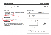
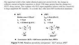
Hans, Marcel, there is not much reason to repeat those thorough investigations mentioned hereabove again, I think we all did our kind of research decades ago as well. The linked data are just facts. Until now I routinely find the issue with BJT input bad RFI immunity in some higher gain circuits for instrumentation. And I think all of us who live near to strong AM radio transmitters know the situation when BJT input phono preamp adds a local radio demodulation into the signal, though JFET input preamp is silent.
A small relevant screenshot from the linked document is attached.
Attachments
Last edited:
O.k. thank you for replying, it seems you have a point.
I will further look into the Blowtorch link that Sottomano gave, intersting info.
Hans
I will further look into the Blowtorch link that Sottomano gave, intersting info.
Hans
JFET’s are better for RFI, but my point is you can take measures to ameliorate the problem with bipolars - no need to write them off.
Last edited:
Oh wow, look that post from Scott 12 years ago, and who was replying to it:
https://www.diyaudio.com/forums/sol...-blowtorch-preamplifier-1002.html#post1641691
Just get your pop-corn and turn the next page 🙂
You were reasonable enough in 2008 , PMA was just the same as it is today...so people never change.JFET’s are better for RFI, but my point is you can take measures to ameliorate the problem with bipolars - no need to write them off.
I have Picked up am radio stations on fet input phono in fairly remote areas so it can still happen. It was also atmospheric bounce and not even local so rather low frequency. NYC can be especially bad if across from the antenna in a penthouse.
Ferrite beads fixed it up.
Now that I know they sound bad I better remove them from all our Stereophile class a rated products.😀
Ferrite beads fixed it up.
Now that I know they sound bad I better remove them from all our Stereophile class a rated products.😀
- Home
- Source & Line
- Analogue Source
- JFET input phono preamp for MM