Ah this one...choose a LCR styren tin foil 2% with a wirewound Rohpoint:: on the ad1862 if you listen to upsampled...not sure a cap is needed. I don t talk about the transimpedance and cap of the feedback for stability some aops need.
As I've mentioned previously, ideally I want to progress this project with mono boards that stack onto a JLSounds I2SoverUSB board, which means I can keep everything compact and dispense with the shift registers - miro1360 has already kindly shown how to attach the JLSounds directly to his PCB bypassing the shift registers.
To work with mono DAC boards I will need to produce my own PCBs and given that miro1360 has already done a good layout and to account for my own lack of expertise on PCB layout/design, with his permission, I would like to simply clone one half of his PCB layout (minus the shift registers) and add the header connections to stack with the JLSounds board. Is that OK with you miro1360?
BTW, that means I will retain the op-amp output section as well.
Having just said that I would retain miro1360's op-amp output section, I would also be interested in trying a tube-based output, however, I've not uncovered any examples of DIY projects partnering the AD1862 with a tube output - does anyone have any suggestions?
There are obviously loads of examples of tube outputs for other DACs, just not the AD1862 specifically and I wonder if there is an underlying reason for that?
There are obviously loads of examples of tube outputs for other DACs, just not the AD1862 specifically and I wonder if there is an underlying reason for that?
I only found this: DAC End - the AD1865N-K with single ended vacuum output stage
I would like to see more possibilities as well..
I would like to see more possibilities as well..
There are obviously loads of examples of tube outputs for other DACs, just not the AD1862 specifically and I wonder if there is an underlying reason for that?
Maybe that ad1862 is obsolete, rare, hardly available..? 🙂
Is that OK with you miro1360?
Yes @nautibuoy, it is OK and you can add header, clone it, and do whatever you want 🙂 It's a free design for everyone.
I'm always worried of stacking in high performance audio. Digital board over analog traces can easily transfer interference into the analog part. It is better to keep the PCBs in one plane.
... or stacking only digital over digital, and analog over analog (avoiding digital over analog)
... shading, which is not easy because you can easily create an antenna 😀
... maybe a multilayer PCB can help (like 6 layers), but it is expensive
If you notice, all the best audio companies avoid PCB stacking although it would save them space and costs.
I only found this: DAC End - the AD1865N-K with single ended vacuum output stage
It is passive resistor I/V with a tube buffer. It would be nicer to have a proven active tube based I/V.
Last edited:
Just wanted to add, that this thread by Sidiy and fellas..
Was a long and beautiful 'saga' about their 1862 project.
Lit's of considerations there are very relevant also today.
DIYHiFi.org • View topic - Building ourselves some CD-Players: The journal
Ciao, George
Was a long and beautiful 'saga' about their 1862 project.
Lit's of considerations there are very relevant also today.
DIYHiFi.org • View topic - Building ourselves some CD-Players: The journal
Ciao, George
good input, time also to re read Thorsten Losch about tube I/V tasks surely, but no surprise : more expensive, more dangerous, more bulky, more noise and certainly more good music as well....
I don't know if one ever try to adapt OTL design to I/V or if it is possible either !
I don't know if one ever try to adapt OTL design to I/V or if it is possible either !
Yes @nautibuoy, it is OK and you can add header, clone it, and do whatever you want 🙂 It's a free design for everyone.
Thank you.
... or stacking only digital over digital, and analog over analog (avoiding digital over analog)
That's how I would do it.
I only found this: DAC End - the AD1865N-K with single ended vacuum output stage
I would like to see more possibilities as well..
Yes, I saw that one. For a simple resistor based I/V there is also the option of using one of the Lampizator circuits.
I only found this: DAC End - the AD1865N-K with single ended vacuum output stage
Also, I believe the AD1865 is V-out whereas the AD1682 is I-out?
I received my JLSounds I2SoverUSB board and am trying to connect it to this dac board, but I’m not having success. It’s using BUS power for the USB section and an external psu for the oscillators and reclock, this is confirmed to work. I also have confirmation the Mac sees the I2SoverUSB.
The input header is wired like this:
I2SoverUSB BCLK —> BCK Dac
I2SoverUSB DATA —> DATA Dac
I2SoverUSB LR ——> LRCK Dac
GND ——> GND
If I turn the volume up high I hear faint distorted music!
Obviously, I’m doing something incorrectly??
Does anyone have experience configuring this I2S board?
The input header is wired like this:
I2SoverUSB BCLK —> BCK Dac
I2SoverUSB DATA —> DATA Dac
I2SoverUSB LR ——> LRCK Dac
GND ——> GND
If I turn the volume up high I hear faint distorted music!
Obviously, I’m doing something incorrectly??
Does anyone have experience configuring this I2S board?
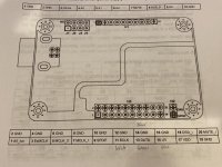
Attachments
JLSounds I2S has galvanic isolation between input and output (separated GND).
First try to power the isolated part (output) from an internal regulator.
This isolated output must be powered (either from internal regulator, or from external (+5V DAC)), connect the internal regulator:
Connect H1:1 with H3:17 (VDD)
Connect H1:2 with H3:2 (GND)
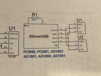
Your second picture is not the reference, it is reference only for direct connection without the glue logic (see my post #538) ...
The reference for DAC with glue logic still be this (without R1):
I2SoverUSB BCLK (H3:11) —> BCK Dac
I2SoverUSB DATA (H3:13) —> DATA Dac
I2SoverUSB LR (H3:15) ——> LRCK Dac
GND (H3:14...) ——> GND
But now in manual is section with different I2S protocols, do the following configuration from the page 5:
"JLsounds AK4396 DAC board I2S mode (old I2SoverUSB board)"
J3:Open, J4:Open, B1:Close, B2:Close, B3:Close, B5:Open
... this should be the standard I2S mode in 64-bit frame
If that worked, you can try to power the isolated part (H3:17 and H3:2) from +5V DAC board 🙂
First try to power the isolated part (output) from an internal regulator.
This isolated output must be powered (either from internal regulator, or from external (+5V DAC)), connect the internal regulator:
Connect H1:1 with H3:17 (VDD)
Connect H1:2 with H3:2 (GND)
Your second picture is not the reference, it is reference only for direct connection without the glue logic (see my post #538) ...
The reference for DAC with glue logic still be this (without R1):
I2SoverUSB BCLK (H3:11) —> BCK Dac
I2SoverUSB DATA (H3:13) —> DATA Dac
I2SoverUSB LR (H3:15) ——> LRCK Dac
GND (H3:14...) ——> GND
But now in manual is section with different I2S protocols, do the following configuration from the page 5:
"JLsounds AK4396 DAC board I2S mode (old I2SoverUSB board)"
J3:Open, J4:Open, B1:Close, B2:Close, B3:Close, B5:Open
... this should be the standard I2S mode in 64-bit frame
If that worked, you can try to power the isolated part (H3:17 and H3:2) from +5V DAC board 🙂
Last edited:

This is what I’ll try now:
-Remove R1 4K7
-Disregard the manual’s setup for AD1862
-Follow manual’s setup for AK4396 I2S mode
I’m on it now, hopefully good news to report.
Thanks Miro!!
-Remove R1 4K7
-Disregard the manual’s setup for AD1862
-Follow manual’s setup for AK4396 I2S mode
I’m on it now, hopefully good news to report.
Thanks Miro!!
- Home
- Source & Line
- Digital Line Level
- DAC AD1862: Almost THT, I2S input, NOS, R-2R