Please someone provide me the pdf file of the ax11 that i have uploadView attachment 857271
this I made a long time ago here are the files the coil you can put it separate 🙂
"edited" I found it with coil even better
Attachments
-
AX-11 component guide.pdf125.3 KB · Views: 521
-
AX-11 silkscreen.pdf208.8 KB · Views: 393
-
AX-11 toner copper.pdf114.8 KB · Views: 421
-
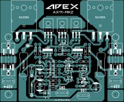 AX-11.jpg438.2 KB · Views: 1,542
 -
AX-11 toner copper with coil.pdf103.4 KB · Views: 402
-
AX-11 silkscreen with coil.pdf153.4 KB · Views: 420
-
AX-11 component guide with coil.pdf129.3 KB · Views: 432
Last edited:
Vargasmongo3435 very much thanks for the files that you share to me and to all of us in this diy community who might need this files
With regard
Surjitsharmaph
With regard
Surjitsharmaph

Help please
I would like to finish ax-14 today and WHERE I should check mV and what should be the value please?
I had it written down, but I lost the paper 🙁
Images just for info:


I would like to finish ax-14 today and WHERE I should check mV and what should be the value please?
I had it written down, but I lost the paper 🙁
Images just for info:
I would like to finish ax-14 today and WHERE I should check mV and what should be the value please?
I had it written down, but I lost the paper 🙁
hi some say 15mV some one said 10mV. on the 5W resistor. i make 13mV on 5watt resistors.
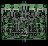
There is an error in the image the diode on the right is wrongI would like to finish ax-14 today and WHERE I should check mV and what should be the value please?
I had it written down, but I lost the paper 🙁
Images just for info:
I would like to finish ax-14 today and WHERE I should check mV and what should be the value please?
I had it written down, but I lost the paper 🙁
Images just for info:
i cant open the images. best to attach to the forum's attachment tool.
i cant open the images. best to attach to the forum's attachment tool.
I am using a tool for attaching images 😉
I upload an image and than I will add direct link to image.
There is an error in the image the diode on the right is wrong
yes, it should be connected other way round. Anode to collector of 2SA1943
I am using a tool for attaching images 😉
I upload an image and than I will add direct link to image.
proper method...🙂
How to attach images to your posts.
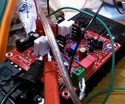
One channel of an AX-14 is done and singing. I think I screwed up the adjustment pot by turning it too much as now turning it doesn't do anything. Although on the plus side it is stuck at 20mV and it sounds great.
Time to start assembling the other channel and shopping for a case
Time to start assembling the other channel and shopping for a case
hi invader,
which pcb did you build?
Also some pics?🙂
best deal for case would be thrown out old amps / electronic markets if there is one near you.
which pcb did you build?
Also some pics?🙂
best deal for case would be thrown out old amps / electronic markets if there is one near you.
Just from listening to the one channel the sound is very tight and defined. A huge step up from my chip-amp builds. That is a good tip on cases. At first the prices didn't look too bad but once I size one big enough to also hold the transformer and power supply they get expensive fast.
Attachments
Last edited:
Hello my friends, hello APEX.
Please tell me about the APEX AX20P amplifier, when the power is turned on, the protection provides a delay of 3 ... 4 seconds, which is good, but when the power is turned off, a slap is heard in the speakers. tell me how to get rid of the slap in the speakers when the power is turned off. I am using not stabilized power supply with 20000uF capacitors per shoulder.
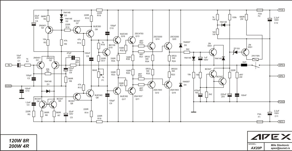
Please tell me about the APEX AX20P amplifier, when the power is turned on, the protection provides a delay of 3 ... 4 seconds, which is good, but when the power is turned off, a slap is heard in the speakers. tell me how to get rid of the slap in the speakers when the power is turned off. I am using not stabilized power supply with 20000uF capacitors per shoulder.
Last edited:
Hope to provide the PP12 PCB and PUS, adjustment parameters of this ear amplifier, thank you!
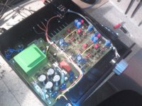
Greetings my friends. I finished assembling the headphone amplifier. I liked the sound, good power, no distortion. Tested with Pioneer headphones, 32R impedance.


Thanks to APEX for this project, thanks to AlexMM for the PCB layout.
I want to add that initially the board has a small error, there is no connection of two diodes with GND in the protection circuit, I have completed the missing jumper.
Clean build!
PSU on the left side?
Yes. PSU on the left side
- Home
- Amplifiers
- Solid State
- 100W Ultimate Fidelity Amplifier