In my limited electronics design experience, I've been doing digital for decades. I've just acquired an interest in tube amplifiers, and analog circuits in general. As all of you know this is far more intricate than digital.
One easy thing for someone like me is to forget about PP vs RMS. I ordered a Hammond transformer from Digikey that, with a CLC without load outputs around 530Vdc.
I was originally modelling around 375Vdc for B+.
I was planning on working with some 12AX7s and KT88s. I know the KTs can handle it, but definitely not the 12AX7s.
I've bought Merlin's and Morgan's books and understand the predicament I'm in, particularly around the DC load line and if the cathodes aren't heated up, and voltage drops that come with that. The KT88s should be fine but the 12AX7 would not appreciate a 530Vdc potential.
I'm also using silicon diodes as a rectifiers, so there is no heat up delay.
I basically bought the wrong transformer, I meant to get one at a much lesser volt.
I realize there are many ways I can approach this, including just buying another PT, setting up a delay circuit, etc.
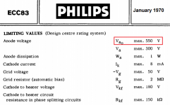
In my mind, based on what I've learned, I'm already screwed. A 12AX7 has a max plate voltage of 300V, assuming no current flow. With the PS I have I'm far in excess of that, no matter what I do.
I'm just wondering if anyone can suggest the most economical and safe way to move forward, just to get by, while I refine my schematic, without buying a new PT. I've already learned(re-learned) a few lessons, which is why I'm asking for more knowledge.
Bottom line - how can I continue testing with this circuit and guarantee that I won't overvoltage my 12AX7? Did I blow it with my ill transformer choice or is there a way around it?
One easy thing for someone like me is to forget about PP vs RMS. I ordered a Hammond transformer from Digikey that, with a CLC without load outputs around 530Vdc.
I was originally modelling around 375Vdc for B+.
I was planning on working with some 12AX7s and KT88s. I know the KTs can handle it, but definitely not the 12AX7s.
I've bought Merlin's and Morgan's books and understand the predicament I'm in, particularly around the DC load line and if the cathodes aren't heated up, and voltage drops that come with that. The KT88s should be fine but the 12AX7 would not appreciate a 530Vdc potential.
I'm also using silicon diodes as a rectifiers, so there is no heat up delay.
I basically bought the wrong transformer, I meant to get one at a much lesser volt.
I realize there are many ways I can approach this, including just buying another PT, setting up a delay circuit, etc.
In my mind, based on what I've learned, I'm already screwed. A 12AX7 has a max plate voltage of 300V, assuming no current flow. With the PS I have I'm far in excess of that, no matter what I do.
I'm just wondering if anyone can suggest the most economical and safe way to move forward, just to get by, while I refine my schematic, without buying a new PT. I've already learned(re-learned) a few lessons, which is why I'm asking for more knowledge.
Bottom line - how can I continue testing with this circuit and guarantee that I won't overvoltage my 12AX7? Did I blow it with my ill transformer choice or is there a way around it?
The high powered and very heavy Ampeg V2 has six KT88/6550 output valves, ECC82/12AU7 phase splitter/driver and ECC83/12AX7 pre amp valves running with a 650volt HT off load and over 30 years the ECC83/12AX7s have not suffered.
Mullard do not give an open load value on Anode/Cathode values.
I know from playing with valves and an EHT power supply as an apprentice, (the best way to learn), I found that double triodes we used in our valve 'computer' (ECC81s) withstood 2k5 DC Anode to Cathode before arcing.
So I wouldn't worry as long as the Anode /Cathode working voltage is less than 300 and the current is within the chosen valve specification.
You can get that 375 VDC from that 375 VRMS, with a pseudo choke I/P filter. A pseudo choke I/P filter is cLC. That 1st cap. will be smaller than 1 μF. The exact value needed is determined empirically. Start with 0.1 μF. and tweak away. Use a high WVDC part to prevent failure, if and when an inductive kick back spike occurs.
Go to Heyboer or other competent winder of magnetics for a choke I/P service suitable 10 H. inductor of adequate current handling capability. Choke I/P service beats the living guano out of inductors. So, "an off the shelf" Hammond part has to be derated. Put a 10 Kohm bleeder resistor of sufficient power rating across the 1st filter capacitor. That value for the bleeder ensures the critical current needed for good regulation gets drawn.
Unlike cap. I/P filters, choke I/P filters allow access to the full RMS current of the power transformer's B+ rectifier winding. Therefore, you more than make up the 38 mA. lost in the bleeder.
FWIW, choke I/P filters are a simple way to get a reasonably well regulated B+ rail. They are frequently found in radio transmitters to assist in carrier frequency stability..
12B4 Preamp – Design/Pre-build Questions
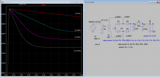
I run the simulation as suggested, see if any help. For other values you can run the sim again if you know LTspice or call us again.
I run the simulation as suggested, see if any help. For other values you can run the sim again if you know LTspice or call us again.
Attachments

Last edited:
You can use a mosfet regulated supply for the front end. Solves a lot of problems. A smaller cap on the mosfet gate can filter more hum and noise than a big one in a CRC filter. No worry about power supply time constants affecting low frequency stability when you close the feedback look. And less stress on your coupling caps during warm up. It is also a good way of regulating Vg2 for your output tubes, if you run in pentode (separate regulator recommended here). There are several good designs out there, many of them adjustable, although brute forcing it with a string of zeners and RC filter on the gate (and protection diodes) works just fine in practice.
If you do this, look for mosfets with fully encapsulated TO-220 packages, good for 650 volts, with a relatively HIGH on resistance. Good for a handful of amps is best, not the biggest monsters you can find. Those will have poor ruggedness in linear mode - smaller ones actually fare better. If you draw more than 50mA, put a resistor in the drain to soak up about half the excess voltage at the max expected current draw (important for screen regulators - your mosfet will thank you by not shorting out). The resistor also provides a safety feature if you use an overvoltage crowbar - you can short the resistor to ground not the mosfet.
KT88’s are happier with the full 500 volts anyway, and getting 60-70 watts should be a breeze. On 375V, cheaper 6L6’s would do just fine.
I was planning on working with some 12AX7s and KT88s.
Is this for HiFi or a guitar amp?
The Tubelab SSE board is a Single Ended HiFi amp that uses a 375-0-375 volt power transformer (often a Hammond 274BX) with two KT88's and a 12AT7. The B+ runs 430 to 450 volts with a 5AR4 tube rectifier and around 460 volts with a solid state rectifier. The kT88's have no problem with this voltage, and with cathode bias and losses in the OPT, the voltage across the tube is under 400 volts.
The plate load circuit on the 12AT7 brings the actual plate voltage on the 12AT7 to somewhere in the 150 to 225 volt range.
Yes the tubes see nearly 500 volts when the amp is first switched on, but this is not a problem.
In almost all guitar amps the preamp tubes are running on a lower voltage supply due to all the resistors in the B+ chain. These resistor values can be adjusted to your particular needs.
A similar situation can be used in a HiFi amp.
There's a very easy way around this. For such an amplifier as the one you're working on, you'll have raw B+ and then chokes and resistors that drop the voltage along the way until it gets all the way up to your first stage. The problem that you have is that you need current draw to get that voltage drop, and you won't have it at turn on.
Say your last node for the 12AX7s is supposed to be 300V DC and your B+ is 530V DC. What I would suggest doing is setting up a stack of zener diodes at the last power supply node to pull the voltage down to 350V. When the tubes start conducting, the voltage at that node will fall on its own and the zener diodes will just fall out of the circuit electrically.
Say your last node for the 12AX7s is supposed to be 300V DC and your B+ is 530V DC. What I would suggest doing is setting up a stack of zener diodes at the last power supply node to pull the voltage down to 350V. When the tubes start conducting, the voltage at that node will fall on its own and the zener diodes will just fall out of the circuit electrically.
You can use the OLD guitar amplifier trick: add a Standby switch, which controls the HV voltage.
You turn main Power switch ON, wait 40 seconds for filaments to warm up, turn Standby ON.
That said, why CLC?
You do NOT want to start with a C which inevitably will charge to peak voltage.
Start with L and simply wait 40 seconds to create a current demand which will let it do its job.
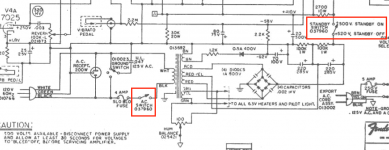
That will be the best option since it will "erase" your RMS to Peak confusion 🙂 but IF you go the C input and higher voltage route, look at the classic Fender Twin Reverb power supply , including the Standby switch.
You turn main Power switch ON, wait 40 seconds for filaments to warm up, turn Standby ON.
That said, why CLC?
You do NOT want to start with a C which inevitably will charge to peak voltage.
Start with L and simply wait 40 seconds to create a current demand which will let it do its job.
That will be the best option since it will "erase" your RMS to Peak confusion 🙂 but IF you go the C input and higher voltage route, look at the classic Fender Twin Reverb power supply , including the Standby switch.
Attachments
As Ketje says, the tubes are actually rated for 500 volts when not conducting. Thousands of amps do this every time they are turned on, and 12AX7's do not explode!
The tubes don’t, but capacitors can. In order to keep it safe, all supply electrolytics need to be two 400 or 450V units in series, and all blocking caps 800V if you don’t have a lower voltage supply available.
Another approach is to buck down the secondary voltage, has better regulation and lower initial peak surge. I use 3x1000u/200V=330u/600v in series and resistor dividers for 2nd capacitor, very quiet, it's also much cheaper than 450v cap of same value.
Attachments


All PS with SS rectification will spike at startup.
It is not really a problem for the 12AX7 as it does not conduct either, so no max dissipation isn't reached.
And as soon at the tubes conduct, all voltage drops at the PS resistors B+2 B+3 happens so all things fall into place.
As other suggested, I would go with for a choke input PS design in your case.
The high powered and very heavy Ampeg V2 has six KT88/6550 output valves, ECC82/12AU7 phase splitter/driver and ECC83/12AX7 pre amp valves running with a 650volt HT off load and over 30 years the ECC83/12AX7s have not suffered.
That is a far different Ampeg V2 than any I have ever seen.
The V2 was a 50 or 60 watt guitar amp that used a pair of 6L6GC's IIRC. The SVT is the 6 tube bass monster he is thinking about.
Or, he could have meant the V9 guitar monster. Take an SVT and add reverb and a distortion channel.
Thanks every one for your replies. It sounds unlikely that I'm going to blow out my tubes during warm up.
Ketje specifically posted from a datasheet that showed an "open anode voltage" limit, which the datasheets I was using(Sylvania and many others) definitely do not have. (It seems like 12AX7 versions don't specify this, while ECC83 do, kind of weird). Having played with much higher voltages in the past (with the intention of producing arcs), I thought 300V was surprisingly low. These tubes are much smaller than they looked from photos and there's two triodes, so just wanted to double check.
Thanks again everyone. Every time I post here I gain so much more knowledge than I thought I would.
12B4 Preamp – Design/Pre-build Questions
I run the simulation as suggested, see if any help. For other values you can run the sim again if you know LTspice or call us again.
TIL about these parameters in LTspice, that's really useful.
The transformer I'm using is center tapped, so my circuit (so far) is more or less like this:

I didn't really model this before building it, and would be the first time I've used a center tapped secondary on a PS, so it didn't immediately occur to me the kind of reverse voltage I'll be dealing with(1.1kV on the negative swing 😱). I'm using 1N5406(600V/3A) since I had them laying around(which is why I'm using diodes instead of a tube to begin with).
Anyone recommend a common(ish) diode that can handle this much? Looks like all the popular ones top out at 1000V.
Use series wired pairs of diodes, to get the net PIV you need. I suggest either the 1 A. UF4007 or the 3 A. UF5408. Both of those parts are rated for 1 KV.
UFnnnn parts are drop in replacements for the corresponding 1Nnnnn parts, but they generate MUCH less switching noise.
UFnnnn parts are drop in replacements for the corresponding 1Nnnnn parts, but they generate MUCH less switching noise.
Use series wired pairs of diodes, to get the net PIV you need. I suggest either the 1 A. UF4007 or the 3 A. UF5408. Both of those parts are rated for 1 KV.
UFnnnn parts are drop in replacements for the corresponding 1Nnnnn parts, but they generate MUCH less switching noise.
That's perfect. Going to need to lookup why that works, but it'll do the job in a pinch. I do happen to have a bunch of UF4007s as well, so even better.
- Home
- Amplifiers
- Tubes / Valves
- Wrong transformer