Hi folks,
I'm brand new here, so I may ask you to be gentle...
I've owned a much-loved DH-200 for 35 years, powering a pair of DQ-10's and was not the original owner. So I was not the person that built her. The past few years she's been getting very warm on the right channel, but still sounding fine. I'm of course concerned that something is wrong after all these years. Reading through the posts on the forum here I feel I'm far beyond the knowledge to really dig in to the details of where to begin, though. I don't want to damage the amp, but I do think it needs help.
My question is, where do I start? I want to leave it a stock DH-200, so is there a kit or good source that discusses the process of fixing my unit?
I'm an engineer, so I know which end of a soldering iron is hot, but getting too much into the details of the amp may lose me fast unfortunately. Replacing parts, easy. Care to hold my hand and help a guy out? 😀
Thanks!
Ed
Remove one of the hot channel's B+ rail fuses, and substitute a milliammeter.
Set the P1 bias in the DH-200 for 250mA through the B+ rail fuse holder.
It may be too high at present. This should take care of the temperature difference.
If the current is not too high, maybe the output device mounting screws are loose
from thermal cycling, etc. The 4 rail fuses are 5A FAST blow.
Make up a test jig for the milliammeter by soldering leads to the ends of a blown 3AG fuse.
https://hafler.com/pdf/archive/DH-200_amp_man.pdf
Last edited:
The first thing to check is the bias current flowing in the output stage. If the bias is a little high it will run warmer.
How do you know the 'cooler' channel isn't the one with a 'problem' 🙂
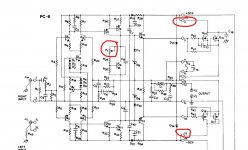
There is a circuit diagram here:
Hafler DH-200 Stereo Power Amplifier Kit Manual | HiFi Engine
Which doesn't seem to detail the adjustment... not that I can see anyway... I guess because these were prebuilt modules maybe.
The adjustment is by means of the preset marked P1 on the diagram on page 14 of the pdf.
The current for lateral FET's is typically 100 milliamps per pair, and there are two pairs per channel.
My recommendation would be to unsolder say connection 13 or connection 4 (either) and and solder in a 0.1 ohm resistor in series. Then by measuring the voltage across that resistor the current can be calculated.
So 20 millivolts would equal 200 milliamps.
Warning... be very very careful in what you do. We see so many well intentioned repairs go wrong due to meter slips and so on. Also the presets may well be a little flaky at this age and either in need of replacement or a good twizz to and fro (amp off if you do that). A flaky preset could be why the bias may be wrong now.
You could also use a DBT (dim bulb tester) as a safety net until you get the feel of the adjustments.
Final adjustment on full mains though.
How do you know the 'cooler' channel isn't the one with a 'problem' 🙂
There is a circuit diagram here:
Hafler DH-200 Stereo Power Amplifier Kit Manual | HiFi Engine
Which doesn't seem to detail the adjustment... not that I can see anyway... I guess because these were prebuilt modules maybe.
The adjustment is by means of the preset marked P1 on the diagram on page 14 of the pdf.
The current for lateral FET's is typically 100 milliamps per pair, and there are two pairs per channel.
My recommendation would be to unsolder say connection 13 or connection 4 (either) and and solder in a 0.1 ohm resistor in series. Then by measuring the voltage across that resistor the current can be calculated.
So 20 millivolts would equal 200 milliamps.
Warning... be very very careful in what you do. We see so many well intentioned repairs go wrong due to meter slips and so on. Also the presets may well be a little flaky at this age and either in need of replacement or a good twizz to and fro (amp off if you do that). A flaky preset could be why the bias may be wrong now.
You could also use a DBT (dim bulb tester) as a safety net until you get the feel of the adjustments.
Final adjustment on full mains though.
Attachments
According to the instructions there are thermal breakers attached to the heatsink that shut the amplifier down,if they are not operating then it hasn't reached that heat limit.
Usual case is insipid HF oscillation -IE- Hasn't reached full blown oscillation or it could be a fault in the bias.
If you don't have an oscilloscope use an AC millivoltmeter to measure for any AC signal at the output --check if the resistor in the zobel circuit is heating up.
Smoothing capacitors could be suspect after this length of time allowing a rise in low frequency AC at the output which would drive the amp to overheat.
If the bias is faulty then a much heavier current is being driven through the output mosfets driving it into class A over a higher wattage range than normal .
The above checks are basic if you don't have a range of audio testing equipment .
Remove one of the hot channel's B+ rail fuses, and substitute a milliammeter.
Set the P1 bias in the DH-200 for 250mA through the B+ rail fuse holder.
It may be too high at present. This should take care of the temperature difference.
If the current is not too high, maybe the output device mounting screws are loose
from thermal cycling, etc. The 4 rail fuses are 5A FAST blow.
Make up a test jig for the milliammeter by soldering leads to the ends of a blown 3AG fuse.
https://hafler.com/pdf/archive/DH-200_amp_man.pdf
Will do... I do this without a load on the output terminals? (no speakers)
The first thing to check is the bias current flowing in the output stage. If the bias is a little high it will run warmer.
How do you know the 'cooler' channel isn't the one with a 'problem' 🙂
There is a circuit diagram here:
Hafler DH-200 Stereo Power Amplifier Kit Manual | HiFi Engine
Which doesn't seem to detail the adjustment... not that I can see anyway... I guess because these were prebuilt modules maybe.
The adjustment is by means of the preset marked P1 on the diagram on page 14 of the pdf.
The current for lateral FET's is typically 100 milliamps per pair, and there are two pairs per channel.
My recommendation would be to unsolder say connection 13 or connection 4 (either) and and solder in a 0.1 ohm resistor in series. Then by measuring the voltage across that resistor the current can be calculated.
So 20 millivolts would equal 200 milliamps.
Warning... be very very careful in what you do. We see so many well intentioned repairs go wrong due to meter slips and so on. Also the presets may well be a little flaky at this age and either in need of replacement or a good twizz to and fro (amp off if you do that). A flaky preset could be why the bias may be wrong now.
You could also use a DBT (dim bulb tester) as a safety net until you get the feel of the adjustments.
Final adjustment on full mains though.
I did see some comments about that P1 pot becoming noisy. Must I worry about adjusting it if it's noisy and causing current to jump high and low because of noise? I see it's got lock/potting compound on it. Just cautious. 🙂
According to the instructions there are thermal breakers attached to the heatsink that shut the amplifier down,if they are not operating then it hasn't reached that heat limit.
Usual case is insipid HF oscillation -IE- Hasn't reached full blown oscillation or it could be a fault in the bias.
If you don't have an oscilloscope use an AC millivoltmeter to measure for any AC signal at the output --check if the resistor in the zobel circuit is heating up.
Smoothing capacitors could be suspect after this length of time allowing a rise in low frequency AC at the output which would drive the amp to overheat.
If the bias is faulty then a much heavier current is being driven through the output mosfets driving it into class A over a higher wattage range than normal .
The above checks are basic if you don't have a range of audio testing equipment .
Thanks duncan, I think the output sounds fine - would oscillations be apparent in the sound if that was the case? I'm leaning towards the bias issue.
Will do... I do this without a load on the output terminals? (no speakers)
The amp is stable with no load. I'd never service an amp with a speaker attached.
You can always use a dummy resistive load if you have one. Short the inputs first.
If the pot seems flaky, I'd replace it before proceeding. I like the hermetic Bourns 3329 (if it fits),
never any problems with those even after decades. Forget the backlash prone multi-turn types.
https://www.bourns.com/docs/technic...ers/publications/bourns_cermet_short_form.pdf
Last edited:
Hi,
Amp is up in years. Recap electrolytics on driver boards and reset Bias. You most likely will need to change the Bias adjustment pots as well. My two cents...
David
Amp is up in years. Recap electrolytics on driver boards and reset Bias. You most likely will need to change the Bias adjustment pots as well. My two cents...
David
The past few years she's been getting very warm on the right channel, but still sounding fine. I'm of course concerned that something is wrong after all these years.
I ran my DH-200 like that for years, with a fan on the hot side. At one point it was serviced, but the hot channel remained, so they obviously didn't fix the problem.
jeff
Your right Vinylkid58 the company actually stated they were aware of this and brought out the "uprated " model DH-220 .
But the actual design was inclined to heat up that's why they fitted safety devices , they would rather it outputted many watts and had a good bottom end which did work although plenty of people did complain about the heat .
I don't think it was-ever"fixed " (correct me if I am wrong ) but the design was popular because of its low end power.
I did see some comments about that P1 pot becoming noisy. Must I worry about adjusting it if it's noisy and causing current to jump high and low because of noise? I see it's got lock/potting compound on it. Just cautious. 🙂
It could be a problem for the following reason... the circuit shows the preset located in the circuit position where if it went open, it would generate maximum bias. When Q9 is off, bias is at a maximum, and that is just what happens when we remove the base current to Q9.
Ideally the preset should be where R30 is and R29 left as fixed value. That way an open circuit preset causes a minimum bias condition.
If you want to adjust the bias I would first of all free off the preset (crack the locking compound) and then turn the pot a dozen times to and fro.
Then set it to minimum resistance which according to the circuit will be the setting to give minimum bias current.
From this position make the adjustment.
Note... it is ALWAYS worth checking the preset is as drawn on the diagram. These days a designer would be criticised for locating it where it is although years ago we never used to bother. Always check though.
FYI, they are supposed to run warm too touch with the proper bias. I recently re-built two DH-200's with our DH-220C design, they run at up to 200mA bias per MOSFET device.
The side that is not warm is under biased, measure as instructed in a earlier post.
The bias pot is probably okay, if it jumps around, you could try to clean it with contact cleaner. Note that measuring at the fuse, it will include the current that is drawn by the driver circuit, probably around ~30-40mA, I am guessing.
We designed a special output stage pcb that adds some features, it makes measuring the OPS bias current much more easily than what Hafler had originally done. Basically a 0.1 ohm R in series with one of the supplies and a couple of test points to measure at.
The thermal breakers are for safety, watch out there is live line AC on them and NO protection, as in insulation, at the solder points = stupid. The breakers only activate if the HS temp gets too hot from an over-load condition. But the heatsinks are a good size, so it is very unusual for the thermal breaker to activate.
Last edited:
I've adjusted the bias on the right channel to great success last evening, thanks all!
Unfortunately the P1 pot reaches its end before I get to 250mA, it went to 290mA, but that is also without a proper warm-up. I'll go back in tonight after doing a warm up to see if it changes.
When I first measured the current it was over 500mA!
A couple of questions:
There are two rail fuses - does it matter which one I measure the current on?
Is audio quality affected by the accuracy of the 250mA bias spec? (curious here)
thanks again for the help,
ed
🙂
The fuse doesn't matter because the current draw will be similar on each rail.
The setting does affect the audio but having said that, once you have more than few 10's of milliamps flowing the difference is absolutely minimal.
Lateral FET's are unique in that they have both a negative and positive temperature coefficient and these tend to balance out around the often quoted 100 milliamps per pair value. That ensures a very stable bias point without the need for extra circuitry.
A side question: Why aren't there current balacing resistors in the power devices' source leads? Aren't they necessary with lateral FETs? Why not?
Best regards!
Best regards!
The resistors aren't necessary when paralleling lateral FET's. If one device draws more current than the other then it's negative tempco automatically starts to lower the current in relation to the other device. The opposite of bjt's.
Thanks, Mooly!
I've been asking 'cause any ELEKTOR design around these 2SJ50/2SK135's uses low value source resistors, even the Mini Crescendo with only one pair. Anyway, there was a design in another German electronics DIY magazine as well with five pairs per channel that didn't feature balancing resistors, which has made me wondering.
Best regards!
They actually slightly reduce the available transconductance... which is something we don't really want to be doing... but many did seem to use them back then.
Curiously Exicon say this in one of their application notes:
Curiously Exicon say this in one of their application notes:
When parallelling devices for higher output powers it is very important to reduce the inductance between the device source connections. The most effective method of achieving this is to mount the devices directly to a common heatsink bracket, and then insulating this from the main heatsink. As the source is bonded to the case, the inter-device inductance is reduced below the point that will cause problems.
A secondary benefit of this method of mounting is that there is no need for the source terminals to be connected via the PCB, which simplifies the layout.
- Home
- Amplifiers
- Solid State
- Hafler DH-200 Getting warm on right channel