Hi,
My raw voltage is 640 VDC, from a 440 Volt secondary with a bridge (8 x HER308 (1000V, 3 A), and a 1000 uF capacitor into a MOSFET follower (with 40 VDC drop) giving 600 VDC for my final tubes.
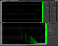
On this 600 VDC I measure approx. 375 mV RMS, measured using a 2 uF capacitor and a 100 kOhm resistor in series. The AC voltage is measured across the resistor. I take this measurement with a 600 VDC @ 120 mA load (72 Watt). I also take measurements across the same 100kOhm resistor with a spectrum analyser, using a Steinberg UR242 USB adapter.
As I am looking into some hum issues I need some common sense advice whether this is a good value or not. As you can see the spectrum is filled with lots of even harmonics (100 - 200 - 300 Hz., etc.).
I tried extra filtering (capacitance) on several positions in, before and after the MOSFET follower, but nothing seems to improve the spectral image.
What do you think is happening?
Regards, Gerrit
My raw voltage is 640 VDC, from a 440 Volt secondary with a bridge (8 x HER308 (1000V, 3 A), and a 1000 uF capacitor into a MOSFET follower (with 40 VDC drop) giving 600 VDC for my final tubes.
On this 600 VDC I measure approx. 375 mV RMS, measured using a 2 uF capacitor and a 100 kOhm resistor in series. The AC voltage is measured across the resistor. I take this measurement with a 600 VDC @ 120 mA load (72 Watt). I also take measurements across the same 100kOhm resistor with a spectrum analyser, using a Steinberg UR242 USB adapter.
As I am looking into some hum issues I need some common sense advice whether this is a good value or not. As you can see the spectrum is filled with lots of even harmonics (100 - 200 - 300 Hz., etc.).
I tried extra filtering (capacitance) on several positions in, before and after the MOSFET follower, but nothing seems to improve the spectral image.
What do you think is happening?
Regards, Gerrit
Attachments
Can you show a circuit (at least a sketch)?
600 VDC, 1000 uF cap, and 0.12 A load current has to have about 0.3 V ripple RMS (+-), or somewhere about 0.9 V ripple amplitude (only C-filter, without any active circuits).
600 VDC, 1000 uF cap, and 0.12 A load current has to have about 0.3 V ripple RMS (+-), or somewhere about 0.9 V ripple amplitude (only C-filter, without any active circuits).
Last edited:
Just a note -- you should protect the input of the scope/net analyzer with clamp diodes -- I know from sad experience blowing out the front end of one VNA!
With a Mosfet active filter you can get less than several mV ripple RMS (or even much lesser).
A Mosfet active filter means the presence of a capacitor in the Mosfet gate (neither before nor after).I tried extra filtering (capacitance) on several positions in, before and after the MOSFET follower, but nothing seems to improve the spectral image.
Last edited:
Hi Duncan,
I know; I tried adding extra capacitors on the gate of the MOSFET, but it has no effect at all. I went up to 200 uF, nothing happens. I’ll post a schematic diagram this evening.
Regards, Gerrit
I know; I tried adding extra capacitors on the gate of the MOSFET, but it has no effect at all. I went up to 200 uF, nothing happens. I’ll post a schematic diagram this evening.
Regards, Gerrit
0.06% ripple is pretty good. Your harmonic structure could be to do with rectification - see the sawtooth waveform you are measuring.
Try an RC filter (or two) on the mosfet gate you can use a high value resistor since there is no current involved.

Try another RC filter after the zeners, say at least 10k and a >10uF plastic cap, and see if it makes a difference to the FFT? You could also try an RC filter before your regulator.
I don't remember the exact fornulae at the moment but this circuit must has regulating and filtering ratio about 6 (+-). It is about 20k divided by Zeners total impedance.This is the diagram I'm using right now. The optional capacitor has no effect at all on output ripple.
Perhaps I have to increase the resistor value?
Ripple at input 1000uF cap has to be abot 0.3 V RMS, so at regulator output it has to be about 0.05 V RMS.
Yes, you may increase 20k resistor up to two times, or up to 39-51k. The larger this resistor the higher Zener impedance and so the higher effect may has that optional capacitor.
Resistor R1 (1k) has to be lower I think, somewere between 10R...100R.
With so large R1 there is a sence to put optional cap after this resistor, but not before (and add additional 10R resistor in series with gate).
There is no need in so large output film cap - in can be 1-100 uF electrolyte type.
This active Mosfet circuit is voltage regulator. If you don't need voltage regulation but have a need in onjy filtering then you may get rid of Zeners and add optional cap instead - this will be an active filter or capacitance multiplier (but voltage will flow with mains voltage). (Circuit as presented in previous post).
Filtering effect of Zener regulator is about the same as regulating effect (about 6 for this). But filtering effect of capacitance multiplier is much more better (but with unstable output voltage).
Last edited:
Hi,
This is the diagram I'm using right now. The optional capacitor has no effect at all on output ripple.
Perhaps I have to increase the resistor value?
Regards, Gerrit
You can check the ripple on the gate. If it is less than the output ripple (which I expect it to be) the output ripple is due to the limited Gm of the MOSFET. In that case, nothing you do at the gate will change it. You need a better MOSFET, or switch to a BJT which has much higher Gm but then you need to account for the base current.
Jan
Hi Jan,
Where do you see the Gm of a MOSFET, I can find values for Gfs (transconductance). Is this what you mean?
Regards, Gerrit
Where do you see the Gm of a MOSFET, I can find values for Gfs (transconductance). Is this what you mean?
Regards, Gerrit
Ripple at the gate is 20 mV RMS, at the output it’s slowly (0 - 120 seconds) increasing to approx. 400 mV, starting at 100 mV.
Increasing filter values for the gate has no effect. The 20 mV at the gate gets lowered, but the ripple at the output remains the same.
Perhaps a better MOSFET is required, but I’m not sure what to look for.
Regards, Gerrit
Increasing filter values for the gate has no effect. The 20 mV at the gate gets lowered, but the ripple at the output remains the same.
Perhaps a better MOSFET is required, but I’m not sure what to look for.
Regards, Gerrit
What if you place optional C1 after R1 (but not before R1), at the gate?Increasing filter values for the gate has no effect. The 20 mV at the gate gets lowered, but the ripple at the output remains the same.
What if you remove film (?) C4?
What if you replace film (?) C4 with electrolyte 1-10 uF?
As jan says you have reached the “limit” of your MOSFET. You can try an RC filter before the MOSFET. This would lower the ripple voltage - which would give the MOSFET less “work” to do - but more importantly it should smooth out the ripple waveform (less harmonics).
Ripple at the gate is 20 mV RMS, at the output it’s slowly (0 - 120 seconds) increasing to approx. 400 mV, starting at 100 mV.
Increasing filter values for the gate has no effect. The 20 mV at the gate gets lowered, but the ripple at the output remains the same.
Perhaps a better MOSFET is required, but I’m not sure what to look for.
Regards, Gerrit
That was what I was thinking How much is the headroom between the minimum input (lowest point of the ripple) and the gate- and output voltage?
If you could show those three points in the same graph, that would give a good overview of the situation.
Jan
- Home
- Amplifiers
- Power Supplies
- Ripple measurements on HV supply