Hi Jan,
It’s not necessarilly only about a cap multiplier. It’s about regulation as well. I try to do both and minimize ripple. I don’t think it’s that “easy”. I tried several things for hours and hours, but the ripple is as stable as can be. I cannot improve regulation by changing/adding filtering.
Have you seen my question about the Gm you mentioned?
Regards, Gerrit
Yes I have seen the question, but I would really like to know what's going on, hence the question on the measurements.
I hate going off only to find out that situation was not what I thought it was. No offense.
For a regulator, see my T-reg (see sig line). Easy, simple, un-measureable ripple, adjustable from 0 to 600V, current limit 10mA to 400mA adjustable.
But, to be honest, it took me more than hours ;-)
Jan
I hate going off only to find out that situation was not what I thought it was. No offense.
For a regulator, see my T-reg (see sig line). Easy, simple, un-measureable ripple, adjustable from 0 to 600V, current limit 10mA to 400mA adjustable.
But, to be honest, it took me more than hours ;-)
Jan
Is schematic OP's post #11 cap multiplier?
Yes, combined with a source follower. Definitely not a regulator.
Your schematic in # 21 is a regulator. A sample of the actual output voltage is fed back to difference amplifier Q1 and the output is used (collector Q1) to adjust the output to make the error zero.
Jan
Last edited:
Hi Euro21,
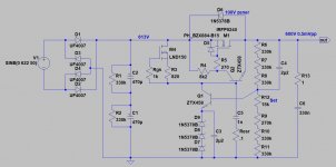
I see the MOSFET is only rated for 200 Volts. What will happen with a capacitive load? Will the MOSFET survive? What is the setting you make with R12? How to determine the right setting?
Is this a “proven” circuit or a concept?
Regards, Gerrit
I see the MOSFET is only rated for 200 Volts. What will happen with a capacitive load? Will the MOSFET survive? What is the setting you make with R12? How to determine the right setting?
Is this a “proven” circuit or a concept?
Regards, Gerrit
What surprises me Gerrit is the aversion to measuring and trying to find out what's going on. Instead jumping to yet another circuit, starting all over again?
Jan
Jan
Jan,
Of course I like to get my circuit working instead of changing everything.
I do have your T-reg. However it only worked for a short period. For some reason the output voltage drops to 0 volts when a load is presented (the same load worked fine before, has not changed and using another simple MOSFET regulator works fine).
I used it with 475 VDC in, 400 VDC out @ 35 mA max.. I guess one of the MOSFET’s of the T-reg is dead.
I didn’t dare to use your T-reg with 640 Volt input to get 600 Volt output @ 400 mA (Class A stage).
My raw voltage for my main regulator is 640 VDC with 0.4 VAC RMS ripple. Output is 600 VDC with 0.4 VAC RMS ripple. Gate voltage is slightly above 600 VDC, with only 20 mV AC RMS ripple.
Regards, Gerrit
Last edited:
It's a concept, points out, that implementing regulating and low output ripple is not an easy job.
The 100V zener across FET protect it (usable stronger kV SiC MOSFET too).
With R12 the correct output voltage adjustable (voltage difference of zener string voltage + Q1 Vbe and the voltage divider makes error).
If you don't want to use regulator, proper cap multiplier also usable, but the ripple rejection very dependent of "sourcing" the capacitor.
See implementing of Ale's cap multiplier:
Cap Multiplier boards (Rev04) – Bartola(R) Valves
No. Zeners work there but not capacitors.Is schematic OP's post #11 cap multiplier?
- Home
- Amplifiers
- Power Supplies
- Ripple measurements on HV supply