Please look at how it works. 🙂OP stated the pulse was 140V which seems too much for many JFETs also MMBFJ177LT1G.
Please look at the preamp schematic and the add-on mute.
Which I called "un-mute" because that´s the way it works.
It *starts* muted (while the pulse appears) since until it´s turned OFF the Fet shows its 0Vgs channel resistance: 300 ohms.
140V?
WHICH 140V? 🙂
The OP measured that voltage across the unloaded output resistor, which means a 1.17mA current is involved, WITHOUT the un-muting circuit .
People often thinks "voltage" while "current" is ignored, while in many cases this explains better what´s happening.
Precisely because of that, I wrote (hate to self quote but when it´s ignored or misunderstood ....):
Will 1.17mA drop 140V across 120k?Physically the problem described comes from a large positive peak coming from preamp +V applied at turn-on, generating a current which passes through last tube plate resistor, output coupling capacitor, power amp input capacitor and power amp first input resistor to ground.
So the Power Amp input is briefly positive. (and that causes the problem)
Yes.
Which voltage will it drop across 300 ohms?
Would you believe 350mV?
I somehow suspect the FET can survive that 🙂
Agree that IF it were a series muting system it would be perforated by 140V, no doubt about that, ... but it is not.
It is a shunt mute instead, starts in the minimum resistance mode and will rise its internal impedance (removing itself from the signal path) only after the damaging pulse disappears.
I´m not much into Home Hi Fi, but into Live Sound and recording Studios (that´s what working with Musicians leaves you) so maybe I am biased, here´s two examples or PRO Audio stuff, Mixing Console "channel strips", the Mic/Line preamps,EQ and signal routing which is present 24/36/48 times (or whatever´s necessary) at each Mixer, and you´ll understand why I talked of (dozens, even hundreds of FET switches):
SSL 82E01 channel strip, would you believe SEVEN Fet switches just in this small board section?
Neotek Elite CR Studio Solo module, just by sheer chance, again seven Fet audio switches:
more modern Mixers use audio switching ICs, of course.
Dozens/hundreds of Relays? a nightmare, specially because of the switching noise .
Now 1 or 2 relays, in relaxed Home environment, may be acceptable.
PS: forgive the "last tube plate resistor" comment, I was quoting from memory since Forum hides images while answering, should have opened preamp image in another page, in any case that does not change the analysis one iota.
I´m not much into Home Hi Fi
Now 1 or 2 relays, in relaxed Home environment, may be acceptable.
Case closed! It is too bad pro equipment used semis for switching but it is understandable when looking at price, complexity, size and weight of such devices. You will also find the finest of opamps like NJM4580 and a true army of electrolytic caps for coupling 😉
Just wondering how such a device would sound would it have been made with relays and switches and without opamps. I know the answer.
Last edited:
The integrated amp I built uses 8 relays, and none of them are in the signal path, they are all power management. I'm considering adding a mute function (to kill the preout when using the headphones), and I'll probably just use a DPDT switch. Too easy?
Yes as action and timing is now up to you. Now suppose your partner or one of your children forgets about all this audio blah blah ("I just want to play music from my phone") and a friend is calling and he/she just shuts it down. You see?
But it is also something done to prevent nasties so it will be effective as long as you are the one operating stuff (preferably in unintoxicated state).
But it is also something done to prevent nasties so it will be effective as long as you are the one operating stuff (preferably in unintoxicated state).
Last edited:
Not really, in my case it would just save me from tuning off the power stage while using headphones 🙂 If I was to attempt to automate an auto mute for power on and off, I would use a capacitor after a diode on the relay I wanted to hold longer (power should hold up until after muting relay drops out to avoid "thump").
That's why you don't short them to ground. You short to ground through like 100R 🙂
Damnit, now I feel like attempting this on my IA!
Damnit, now I feel like attempting this on my IA!
Deleted my posts as I misread your setup. You use relays to switch off power to sections in a integrated amplifier ?! This would almost always result in hefty surges and thumps. Or do I misunderstand? English is not the clearest language to explain stuff in I see. It is also a bit off topic. You maybe start a new topic on this. With drawing/schematics/pictures!
One relay does touch to turn on and off
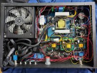
One relay (power stage on/off control) drives 4 other relays, one turns on the DC boost modules for the output stage, the VA/PI, one for bias, and B+ for the output stage (4PDT), and the other three (time delay) switch the output heaters, and two steps of "soft start" resistors (1k5, 750R, short, otherwise the 850W ATX that powers it all trips out for over current).
The switching takes place at LV so there aren't any spikes on power on or off.
EDIT Here's a pic of it... A little messy but works well enough.
Attachments
Last edited:
Funny how you chop my answer in bad faith to make me look like a simpleton while in fact I stated I work with MUCH more sophisticated PRO RECORDING stuff.Quote:
Originally Posted by JMFahey View Post
I´m not much into Home Hi Fi
There is a reason for the complexity of such PRO stuff, size and weight are but a consequence.Case closed! It is too bad pro equipment used semis for switching but it is understandable when looking at complexity, size and weight of such devices.
You are not up to date with PRO Mixers, are you?You will also find the finest of opamps like NJM4580 and a rue army of electrolytic caps as for coupling
Highest quality Op Amps, even custom made or discrete ones are common, basically because commercial offerings are not enough.
Do they use electrolytics in the signal path? 😱
Maybe they are good enough after all 😱 , contrary to "audiophile" lore. 🙄
Of course, PRO Mixers are designed by qualified Engineers and used by qualified Audio Engineers and recording/mixing Professionals, who are performance driven (funny concept, huh?) and have little patience for audiofoolishness.
You will find little "glass" in Recording equipment since, .... when? .... 1957? , TONS of "sand" and NO "mojo parts" such as copper or gold foil capacitors, NOS stuff, silver wiring and similar beauties.
Funny thing is that any and all Musical material later reproduced by "Audiophile" equipment ... comes straight from those "sand castles", go figure. An irony many fail to detect 😀
You can´t "know" the answer, just "imagine" it, because such recording equipment is not being used, as simple as that.Just wondering how such a device would sound would it have been made with relays and switches and without opamps. I know the answer.
As usual, a simple OP problem , with 4 or 5 working solutions which were offered early (now it´s up to him to pick one or none), has slowly but surely drifted in a completely unrelated fundamentalistic tirade.
Oh well.
Why doesn´t this surprise me?
Yes I would advise to take it less seriously and make it less of a tirade as it is you that brought using semis for muting and pro stuff into the equation. Your assumptions are way off but don't let that distract you 😉
Originally Posted by brik View Post
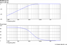
With .22uf into a 30k load the -3db point is 24hz.You realize the low end roll-off starts at 240hz with those values?
It starts becoming more pronounced and a problem at that point.
Should I have started at -0.0000000000000000000001 attenuation as the starting point?My bad.
Thanks for pointing that out.Please advise.Let me know what point I should have started at to explain my point .TIA
With .22uf into a 30k load the -3db point is 24hz.You realize the low end roll-off starts at 240hz with those values?
Erm.
The low-end roll-off of any high-pass filter of any cutoff frequiency "starts" at infinity.
Why you've chosen exactly x10 cutoff frequency as the "start"? Why not x5 or x20?
What's so special about -0.047dB for roll-off "start"?
Can you please elaborate?
It starts becoming more pronounced and a problem at that point.
Should I have started at -0.0000000000000000000001 attenuation as the starting point?My bad.
Thanks for pointing that out.Please advise.Let me know what point I should have started at to explain my point .TIA
It is probably because of the corona and lockdowns that people are into quarrels quite quickly. I experience this too on motorways, supermarkets etc. Not much is needed to cause aggression and useless debate.
So... let's just be constructive and let's design good stuff.
So... let's just be constructive and let's design good stuff.
Does it have to "look" like it? 😀 You have the formula, use it.It doesn't look like it starts at infinity to me...
It's just the voltage divider with one constant and one frequency dependent component. Capacitor impedance does not equal to zero at any finite frequency, so there's some attenuation.
The transfer function graph does get much steeper around the cutoff, but it is never flat.
Any point you feel fit, as long as you can explain why you've chosen exactly it.Let me know what point I should have started at to explain my point
Kids might read us. They might get an impression that first order high-pass filter somehow stops attenuate completely at exactly 10x cutoff frequency. Their lives might go downhill. Do you want to be responsible for that? I don't.
😉
The original post [# 1] of this thread started with the problem that high voltage was appearing at the output of a preamp or amplifier.
Capacitors:
With the exception of:
capacitor's lead inductance,
and parasitic inductance of the capacitor metalization/foil,
Then . . . the capacitor is a short circuit when a DC voltage is first applied.
The only current limiting factors when the DC is first applied to the capacitor are:
The cap lead inductance
The cap metallization/foil inductance
The [series] resistance from the DC source, and any other series resistance of the circuit that the capacitor is in.
This is Physics and Math.
ELI the ICE man. In this case ICE is the cold hard fact (Current Leads the Voltage in any and all capacitors).
No exceptions
It is not nice to (try and) fool Mother Nature.
Last edited:
Does it have to "look" like it? 😀 You have the formula, use it.
It's just the voltage divider with one constant and one frequency dependent component. Capacitor impedance does not equal to zero at any finite frequency, so there's some attenuation.
The transfer function graph does get much steeper around the cutoff, but it is never flat.
For the record, I don't have any formulas besides the odd calculator.
And while you are technically correct, It's flat for all intents and purposes as far as audio goes and diminishing returns etc... 🙂 Just saying...
If -3 is 24Hz, then what is 240Hz precisely since it's not 0db. -0.000001db or something?
Back to the topic. How about a triode (6SN7?) set up as a cathode follower (or diode) using a relay coil as the load? This way the triode would heat up along with the amp and engage the un-muting relay when the tube was hot and conducting. My only problem so far is finding an appropriate relay. All the ones with the right DCR are designed for 220VAC apparently except one that costs like 100$ (eff that).
Last edited:
It's -0.0435dB. Or 0.995 in terms of voltage.If -3 is 24Hz, then what is 240Hz precisely since it's not 0db. -0.000001db or something?
But you could equally choose -0.0873db (0.99) at about 7x cutoff frequency, or -0.0087dB (0.999) at about 22.5x cutoff frequency as the reference point, or any other random number that is "close enough" to 0dB (1).
It's just I will inevitably ask why do you think exactly this "close enough" is enough and others aren't 🙂
20Hz - whatever +- 0.5db is "close enough" and then some. We're talking about audio, not radio, right?
Some Polk speakers are rated at +-6db these days.
Thanks for the precision math though! 0.04db is well within my "ballpark" calculation, the 0.000001 being entirely factitious.
Some Polk speakers are rated at +-6db these days.
Thanks for the precision math though! 0.04db is well within my "ballpark" calculation, the 0.000001 being entirely factitious.
Last edited:
Back to the topic. How about a triode (6SN7?) set up as a cathode follower (or diode) using a relay coil as the load? This way the triode would heat up along with the amp and engage the un-muting relay when the tube was hot and conducting. My only problem so far is finding an appropriate relay. All the ones with the right DCR are designed for 220VAC apparently except one that costs like 100$ (eff that).
Well, I guess I've had enough internet for today.
- Home
- Amplifiers
- Tubes / Valves
- output of valve preamp showing a high voltage when turned on