That´s the way, of course.A slow turn on/fast turn off muting circuit is meant to short preamp output every fast at power off eliminating any nasty surge (audible and/or damaging). It cancels the silly prescribed power on sequence that no family member will do the right way too making the device practically foolproof. Way better to keep marriages OK and children happy.
It is a novelty and therefor hard to swallow for some but it will be big some day 😀
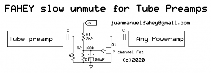
Please let me offer my Slow Unmute cicuit.
Being a dyed in the way Minimalist, it can´t be simpler.
yet it has some advantages over some solutions offered above:
* different to clipping Zeners, this both reduces original DC pulse to Zero (instead of, say, 15V peak which will still thump)and removes itself from the signal path afterwards, so it does not kill typical high Tube preamp headroom by clipping its output.
* different to relays, it does not need extra power (solenoid coil) nor measures to reduce clicking noises
* did I mention it´s CHEAP and simple? 😛
* almost forgot: you do not need to alter existing coupling cap and ground reference resistor values by any means.
* extra note: unmute time is longer vthan any reasonable turn on thump.
Re-mute at turn off is not extra fast (so it won´t block, say, power switch clicking/sparking) buy as far as output peak caused by turning ON-OFF, since it tracks +V, as soon as it (slowly) drops to about halfway, muting resumes.
You can use ANY P Channel Fet, a few types are still available and some are cheap.
Cheaper than a relay and its associated supply for sure.
Attachments
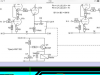
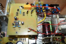
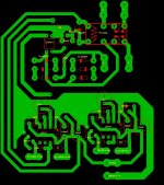
Example from post #10. No sound thinking person uses electrolytic caps in the signal path when it is not absolutely necessary.
Schematic is slow turn on 20sec and fast turn off.
Powered by heater supply
Attachments
Last edited:
Koifarm, I guess we could add that this circuit works with a DC heater supply. Rectifying can be added of course if AC heater supply is used.
Regards, Gerrit
Regards, Gerrit
That´s the way, of course.
Please let me offer my Slow Unmute cicuit.
Being a dyed in the way Minimalist, it can´t be simpler.
yet it has some advantages over some solutions offered above:
* different to clipping Zeners, this both reduces original DC pulse to Zero (instead of, say, 15V peak which will still thump)and removes itself from the signal path afterwards, so it does not kill typical high Tube preamp headroom by clipping its output.
* different to relays, it does not need extra power (solenoid coil) nor measures to reduce clicking noises
* did I mention it´s CHEAP and simple? 😛
* almost forgot: you do not need to alter existing coupling cap and ground reference resistor values by any means.
* extra note: unmute time is longer vthan any reasonable turn on thump.
Re-mute at turn off is not extra fast (so it won´t block, say, power switch clicking/sparking) buy as far as output peak caused by turning ON-OFF, since it tracks +V, as soon as it (slowly) drops to about halfway, muting resumes.
You can use ANY P Channel Fet, a few types are still available and some are cheap.
Cheaper than a relay and its associated supply for sure.
The main disadvantages:
- now there is a nonlinear semiconductor IN the signal path. Varying capacitance depending on voltage over it. One of the reasons that many DIYes remove this kind of muting. In older Japanese audio this was the standard way of muting whereas the high end line often had relays.
- now there is a need for 2 caps in series which need to be double the value. With a relay solution only 1 coupling capacitor is needed for DC blocking. With higher voltage high value capacitors this can be a costly affair.
- the JFET is sensitive to ESD which can be introduced when plugging in a cable.
- at fast power off and on again no adequate muting
- cheap is relative, price/quality ratio of the "under 10 Euro" relay solutions is better.
- it is no substitute for 0 Ohm shorting outputs in terms of effectivity
- JFETs are not exactly to be found in abundance, maybe their price is the same as a small signal relay?!?!
Anyway with tube purists already complaining about "sand amps" the introduction of a semiconductor in the signal path will not be applauded I think 🙂
Last edited:
Is there a market here for an external piece of kit that is a master switch to the hifi units, incorporates relays for managing the on and off sequences, and guarantees that all types of equipment can be connected safely and without the need for alterations?
This would mean centralisation which makes things not easier for the average tube person. IMHO it is better to have every device being autonomically operating and intrinsically safe regardless of what is connected but that already seems a steep way to go.
It would probably involve a microprocessor which can lead to you being accused of witchcraft 😀
It would probably involve a microprocessor which can lead to you being accused of witchcraft 😀
Last edited:
5/10 seconds after Turn On (the problematic period) , the "nonlinear" semiconductor is solidly OFF and so absolutely OUT of the circuit for all practical means.The main disadvantages:
- now there is a nonlinear semiconductor IN the signal path.
From Datasheet a turned off Fet can pass current in the order of 1 PICO Ampere when receiving 20VDS
Can´t imagine how that could affect preamp signal .
Datasheets show typical DS capacitance around 7pFVarying capacitance depending on voltage over it.
Suppose it varies wildly from , say, 5pF to 10pF ... will that affect this preamp signal?
Wow!!! you must have much better ears than me!!!!
I know DIYers removing protection circuits, fuses, etc.One of the reasons that many DIYes remove this kind of muting.
If you are that kind, please be my guest.
Then you can claim it sounds better.
No doubt.In older Japanese audio this was the standard way of muting whereas the high end line often had relays.
They also had polished walnut enclosures, nicer and larger solid aluminum knobs, mirror polished or all black front panels, etc.
It comes with the higher price tag.
Now very high quality Recording Studio mixers, WAY more expensive than those Japanese Home amplifiers , think NEVE, Studiomaster, etc. were happy using dozens to hundreds of FET switches routing Audio all over the place.
FWIW I have used THOUSANDS of Fets with no special reliability problems.
By the way, still do.
2 or 3 Months ago I bought One Thousand JFets from Mouser, go figure.
As a side note, large amounts of relays tend to be a reliability nightmare (compared to solid state switching that is).
You must be joking. 🙂- now there is a need for 2 caps in series which need to be double the value.
The caps I showed (and the ground discharge resistor) are the ones already existing there: the preamp output capacitor and resistor which caused such a heated (and still undecided) debate and the "Any Amplifier" current input cap.
That´s why I drew them the way I did, showing they are not *external/added* capacitors (and resistor).
Read above.With a relay solution only 1 coupling capacitor is needed for DC blocking. With higher voltage high value capacitors this can be a costly affair.
Maybe you need a little more experience with "sand" 🙂 , Junction Fets are quite robust, no microns thick "glass" gate insulation but plain PN junctions which can pass reasonable reverse current (say 1 mA) without being destroyed.- the JFET is sensitive to ESD which can be introduced when plugging in a cable.
Who would think that "sand" can be better than "glass" 😀
Some would get upset hearing such sacrilege. 😀
Nobody asked for that.- at fast power off and on again no adequate muting
Yet I bet that would not be a problem here, the specific problem we are trying to solve here is the large positive peak appearing on initial Preamp turn-on, please read the thread header, and this circuit solves that, period.
My solution is small, simple, and costs less than ONE Euro, go figure- cheap is relative, price/quality ratio of the "under 10 Euro" relay solutions is better.
RS Components has ON brand P channel Fets for
MMBFJ177LT1G | ON Semiconductor MMBFJ177LT1G P-Channel JFET, Idss 1.5 → 20mA, 3-Pin SOT-23 | RS ComponentsPrice Each (In a Pack of 10)
£0.263
(exc. VAT)
Nothing gets as low as metal to metal contact, that´s not news, but I bet 300 ohm in parallel with existing ground reference resistor (was it 1M? 120K?) will DEFINITELY quench that turn on pulse.- it is no substitute for 0 Ohm shorting outputs in terms of effectivity
Again:- JFETs are not exactly to be found in abundance, maybe their price is the same as a small signal relay?!?!
£0.263
MMBFJ177LT1G | ON Semiconductor MMBFJ177LT1G P-Channel JFET, Idss 1.5 → 20mA, 3-Pin SOT-23 | RS Components
Maybe/probably 🙂 , but again, I am answering to a specific question: the OP does not seem to be such a Tube Purist since he´s trying to solve a problem caused by his tube preamp 😱 driving his excellent but sadly full of sand power amplifier 😀Anyway with tube purists already complaining about "sand amps" the introduction of a semiconductor in the signal path will not be applauded I think 🙂
Physically the problem described comes from a large positive peak coming from preamp +V applied at turn-on, generating a current which passes through last tube plate resistor, output coupling capacitor, power amp input capacitor and power amp first input resistor to ground.
So the Power Amp input is briefly positive. (and that causes the problem)
My theory is:
Apparently the time constant of such a phenomenon/event is longer than the time constant of the Power Amp DC protection circuit, and the DC pulse at the output is higher than its trigger level.
So given enough voltage for long enough time (we may be talking 4 or 5 Volts for a second or less) the "Protection" triggers, ..... the phenomenon observed by and worrying the OP.
Shunting that current peak to ground (120k is not enough, 300 ohm will definitely do) solves the OP problem using a literally thumbnail sized board.
In fact, IF he gets a TO92 through hole type P Fet (I have over 100 from "the old days") he does not even need a board, having a total parts count of 1 Fet , 2 resistors an a 100uFx25V electrolytic.
Last edited:
OP stated the pulse was 140V which seems too much for many JFETs also MMBFJ177LT1G. Either one can go left or right but anything done in a non intrusive way to mute at power on/off is better than nothing. Of course I meant the meanwhile rare through hole JFETs as SMD is heresy for most tube people.
I understand your post quite well but using JFETS is not done because it is quality but because of size/price/weight etc. certainly when many are needed and when it concerns semiconductor devices. Nevertheless I have worked as a repair guy and often replaced defective muting JFETs. Till today I never have had to replace a muting relay but this is just anecdotical which proves nothing. I did have to replace much speaker protection relays because of wrong part choices many companies make.
It is surprising to see the most simple solutions are not liked in devices that people often build because they are so simple 🙂 Tubes, switches, one would think an old fashioned robust relay that makes things better is liked but alas. I think everything has been said (at least thrice 😉) and I leave to to the imagination of the readers to decide what is best.
Last edited:
Funny to read "It is surprising to see the most simple solutions are not liked in devices that people often build because they are so simple"OP stated the pulse was 140V which seems too much for many JFETs also MMBFJ177LT1G. Either one can go left or right but anything done in a non intrusive way to mute at power on/off is better than nothing. Of course I meant the meanwhile rare through hole JFETs as SMD is heresy for most tube people.
I understand your post quite well but using JFETS is not done because it is quality but because of size/price/weight etc. certainly when many are needed and when it concerns semiconductor devices. Nevertheless I have worked as a repair guy and often replaced defective muting JFETs. Till today I never have had to replace a muting relay but this is just anecdotical which proves nothing. I did have to replace much speaker protection relays because of wrong part choices many companies make.
It is surprising to see the most simple solutions are not liked in devices that people often build because they are so simple 🙂 Tubes, switches, one would think an old fashioned robust relay that makes things better is liked but alas. I think everything has been said (at least thrice 😉) and I leave to to the imagination of the readers to decide what is best.
The simple solution is to replace the oversized 10uF cap with a 0.47uF.
The existing 120k resistor will discharge the cap faster then the cathode follower can charge it - thus no thump no relay or fet needed. Can it be
more simple ??
With a loading of 30k ( 120k + input impedance of poweramp) the -3dB limit is 11 hz. A 0.22 uF cap would be even more reasonable.
Please measure the proposed setup for any ramp up voltage and then we talk further OK?
Keep things simple but not too simple....
Keep things simple but not too simple....
The cathode follower will take a few seconds and gently charge the capPlease measure the proposed setup for any ramp up voltage and then we talk further OK?
Keep things simple but not too simple....
as the heater warms up. We are talking about seconds here.
With a loading of 30k ( 120k + input impedance of poweramp) the -3dB limit is 11 hz. A 0.22 uF cap would be even more reasonable.
I always thought one of the goals of "Hi-Fi" was to reproduce a flat frequency response from 20hz to 20khz as a minimum starting point.
With .22uf into a 30k load the -3db point is 24hz.You realize the low end roll-off starts at 240hz with those values?
It was bad enough with the .47uf.(Roll-off starts at 120 hz).
Your "simple solution" castrates the bandwidth.1 vote for the relay.
You must be one of those lucky ones that has speakers that reproduces 20 hzI always thought one of the goals of "Hi-Fi" was to reproduce a flat frequency response from 20hz to 20khz as a minimum starting point.
With .22uf into a 30k load the -3db point is 24hz.You realize the low end roll-off starts at 240hz with those values?
It was bad enough with the .47uf.(Roll-off starts at 120 hz).
Your "simple solution" castrates the bandwidth.1 vote for the relay.
without any rolloff. In addition you must also be in posession of music material
that has 20hz recorded. Congratulations.
Would you share what recordings and speakers you have ?
Most of the time i use a mute relay on the output of a preamp.
The problem was at the turn off of the preamp.
The mute relay would not turn off before the main and you get a turn off spike
ore a thumb out of your speaker.
So you could first turn off the power amplifier and than the preamp.
But that would not be very WAF.🙁
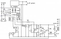
So on a Dutch forum a solution was found
It is a all in solution!
When the amp power is turned off the mute is first turned on before the main power is turned off.
The solution has all so a possibility to insert a timing relay for your High voltage,if you want the tubes pre heated.
But in the schematic you could omit that part.
You could feed the PCB with 6,3v DC from the heather supply or make a tiny
5v dc supply.
It does not matter if the 5v supply is turned off at the same time your preamp power supply turns off,so no external supply is needed !!
Last week i made a pcb an build it in my 6V6 preamp with only the Mute relay.
No spikes,no thumb at turn off,it worked very well,🙂
The problem was at the turn off of the preamp.
The mute relay would not turn off before the main and you get a turn off spike
ore a thumb out of your speaker.
So you could first turn off the power amplifier and than the preamp.
But that would not be very WAF.🙁
So on a Dutch forum a solution was found
It is a all in solution!
When the amp power is turned off the mute is first turned on before the main power is turned off.
The solution has all so a possibility to insert a timing relay for your High voltage,if you want the tubes pre heated.
But in the schematic you could omit that part.
You could feed the PCB with 6,3v DC from the heather supply or make a tiny
5v dc supply.
It does not matter if the 5v supply is turned off at the same time your preamp power supply turns off,so no external supply is needed !!
Last week i made a pcb an build it in my 6V6 preamp with only the Mute relay.
No spikes,no thumb at turn off,it worked very well,🙂
Attachments

You must be one of those lucky ones that has speakers that reproduces 20 hz
without any rolloff. In addition you must also be in posession of music material
that has 20hz recorded. Congratulations.
Would you share what recordings and speakers you have ?
Just realize if you have speakers that are -3db down at 20hz with your brilliant engineering they'll be down -6db at 20 hz(source wise).It adds an additional -3db to the roll off to the original source.
That's the point i'm making.There's a reason relays are in most decent commercially built gear.Another vote for the relay.
Last edited:
And your speakers will reproduce 20hz ?Just realize if you have speakers that are -3db down at 20hz with your brilliant engineering they'll be down -6db at 20 hz(source wise).It adds an additional -3db to the roll off to the original source.
That's the point i'm making.There's a reason relays are in most decent commercially built gear.Another vote for the relay.
Do you have any recording that has 20 hz ? If so, what ?
And your speakers will reproduce 20hz ?
Do you have any recording that has 20 hz ? If so, what ?
"I always thought one of the goals of "Hi-Fi" was to reproduce a flat frequency response from 20hz to 20khz as a minimum starting point.
With .22uf into a 30k load the -3db point is 24hz.You realize the low end roll-off starts at 240hz with those values?
It was bad enough with the .47uf.(Roll-off starts at 120 hz).
Your "simple solution" castrates the bandwidth.1 vote for the relay."
You keep droning on about 20hz.I already explained to you the roll off starts alot earlier.240 hz with a .22uf cap.If that doesn't bother you then enjoy.
But you really should say its for a tube crossover and not a preamp because that's what it would be.
The problem was at the turn off of the preamp. The mute relay would not turn off before the mains voltage and you would get a turn off spike or a thump out of your speakers.
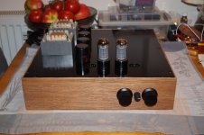
Most adequate muting circuits are slow turn on/fast turn off when using a relay shorting the outputs to GND almost immediately. I haven't ran into issues with the simple circuits but your solution is another decent one. More complex but with extras. Kudos. Nice preamp BTW, built with love.
There's a reason relays are in most decent commercially built gear. Another vote for the relay.
Nothing beats a circuit that prevents nasties to happen at all. Solving problems at the root costs less effort and least possible damage.
A well known dutch designer designed an "always on" power amplifier with very very slow servo to keep output offset at 0V without causing any audible side effects. I had more than once to repair stuff for audio guys as a sequence of power brownouts caused the servo to very slowly compensate the DC surge in .... minutes.....in that time the woofers had already turned into charcoal. In general this also caused family members to experience a horror moment too 😀
Many have since then enjoyed the infamous Velleman K4700 and/or µPC1237 protection circuits 🙂
Last edited:
I design for a -3db of between 1 and 2 Hz. brik is correct. Why would you want to start rolling off in the midbass region?
Furthermore, my speakers (and tube amps) will reproduce 5 Hz if you feed them enough power, and I have plenty of music that goes into the 20s of Hz. There is even a pipe organ recording with 8 Hz as the lowest pipe called "Bach on the biggest".
My headphone amp has an fc of 0.6Hz, and they will produce 5Hz also.
When I turn off my tube amps, they slowly fade away as the B+ bleeds out. The preamp uses relay input switching, so as soon as power is removed, the input it open (only grid leak as the input) so there is no thump.
Last edited:
Erm.With .22uf into a 30k load the -3db point is 24hz.You realize the low end roll-off starts at 240hz with those values?
The low-end roll-off of any high-pass filter of any cutoff frequiency "starts" at infinity.
Why you've chosen exactly x10 cutoff frequency as the "start"? Why not x5 or x20?
What's so special about -0.047dB attenuation as the reference point for roll-off "start"?
Can you please elaborate?
- Home
- Amplifiers
- Tubes / Valves
- output of valve preamp showing a high voltage when turned on