Hi , I have a 120 an early model without the TIP transistors, I am trying to rebuild the unit with parts ordered from Mouser or Newark, looking at the service manual and part numbers both Mouser and Newark have most of these parts, is it safe to use these parts in my Dynaco as replacements for the originals. The parts are as follows;
BC108
2N5320
2N5322
2N3772
2N4073
2N4347(cannot find)is there a suitable replacement for this transistor?
Or is anyone has a complete parts list including caps and diodes that would be great.
Thank You
BC108
2N5320
2N5322
2N3772
2N4073
2N4347(cannot find)is there a suitable replacement for this transistor?
Or is anyone has a complete parts list including caps and diodes that would be great.
Thank You
Start by going to avahifi - Audio Basics Newsletter
Get the file 1984 Audio Basics and read pages pages 17-23.
A summary of the updates is below:
Q1 replace 40233 (100-250 beta) with BC108A (130-180 beta)
Q2 replace 2N3053 (100-200 beta) with 2N5320 (160-260 beta)
Q3 replace 2N3053 with TIP31C
Q4 replace 2N4037 with TIP32C
Q5, Q6 replace 2N3055 (17-25 beta) with 2N3772 (60-90 beta @ 1A)
D1 replace with 1N4733
D2,3 replace with 1N4004
C1 replace with 5 µF 10V tantalum
Add C13 68 pF from Q2C to Q2B, both channels
Add C14 0.01 µF from Q3C to GND, both channels
Add C15 27 pF from Q2C to Q1E, both channels
Add C16 .01 µF across xfmr secondary at rectifier bridge on PC-15
Replace C6 (30 µF, NP) with .47 µF Mylar
Add 3.3 Ohm ½ watt emitter resistor to Q4, both channels
Add 1 kOhm ½ watt resistor across the red/black output jacks
Your amplifier may already have some of the updates. For C1 try to find a film capacitor that fits instead of tantalum.
My question actually is can I use the parts I listed to rebuild my power supply and amp boards without doing the mofset and Tip transistor fixes. My friend wants it original and I'm just asking if the current parts list I have posted will work.
Thanks
Thanks
Much of the reason the upgrades were done by Dynaco is that the amplifier in its earliest version was not very reliable. Read the whole Audio Basics article to get some of the history. Repairing the amplifier without any upgrades would result in an unreliable and potentially unstable amplifier. Will it work? Maybe initially but the long term prognosis would be poor.
Here is another link worth visiting regarding the 120: Dynaco_120
Here is another link worth visiting regarding the 120: Dynaco_120
This Dynaco played perfectly for 10 years before a transistor blew out, wouldn't I expect to see these results with the same components?
I've got one. The problem is not old transistors, IMHO, the problem is if you play it loud or long so much heat builds up it will melt solder. I put a fan on mine and play it 17 hours a day now. I used NTE60's for output transistors, which looking at the datasheet is probably MJ15003g. If I were doing it now I would use MJ15015g output transistors, TIP31c, 32c, or 41c, 42c driver transistors, and a MPS8099 or MPSA06 signal transistor. You have to twist the leads around on TIP TO220 transistors. One one side I have NTE249 input, NTE49 & 50 driver transistors, (with heat sink added) the other side has all original PC15 transistors, only the output transistors are NTE60. The two channels sound the same.
I think the FET power supply mod is stupid, you want a power supply that collapses if you draw too much current (6.25 amps) and the original does that. I had to find a really low gain TO3 transistor for the PC14, but you could put resistor between b-e to cut the gain on a modern transistor. An NTE60 transistor there without gain decrease caused the power supply to collapse at 2.3 amps. (Tested with 8 ohm 225 watt resistors on the big cap). I put fuses on the capacitor charge from PC14 so the collapsed supply doesn't run forever and heat up that board, either.
The picofarad capacitors between b-e on the drivers I feel to be important, slows down the slew rate and prevents RF oscillation with faster modern transistors (you can't buy the old slow ones anyway, even if somebody did stamp the old number on them. The RCA plant has been demolished and is a shopping mall). I put the RC on the output, too.
New e-caps are a basic for reliability on all my old consumer electronics.
If you want to fix it in a hurry, convert it to a LM3886 IC amp, the 70 v power supply is perfect. djoffe sells PWBs as updatemydynaco.com
Before he jumped off the IC cliff, djoffe addressed the vile sound (cold) of this amp due to low idle current on the output transistors. See this thread http://www.diyaudio.com/forums/solid-state/231029-dynaco-120-rebuild.html
I built two 8 transistor bias current setter circuits on perfboard and mounted them on little brackets above the old output caps, because the new caps are so much smaller. I glued the new caps down, they dont fit the brackets.
The sound with 20 ma bias current is really good, I can't tell the difference at the 1.5 vpp is listen at, between this amp with bias circuits, and the Peavey CS800s which has distortion in the .00? % range. The Peavey has no caps in the signal path, the dynaco has 2, no problem IMHO. I did have popcorn noise from some tantalum input caps I bought, I'm using Aerovox gold CPO ceramic caps, 50 v rating (for more linearity) 4.7 uf on the input. I'm using Panasonic storage and output caps, their big ones are still made in the USA! Bought some Panasonic 4700 80v caps last month from newark, USA origin.
I mounted 2 PCAT power supply fans on a channel that sits underneath and outside, and powered them with a 9 v wall transformer from Goodwill, totally outside the enclosure. They blow on the two PC15's. No more melted solder- the wire jumping up off the output cap at the Christmas Cantata was the cause of the last output transistor meltdown, when the wire sprang up and hit the steel top. A board with 4 holes in it above snap-in output caps can stress relieve the solid core wire and help keep it in place if you carry it around.
Have fun.
Last edited:
Something happened to the link to the djoffe 8 transistor bias control circuit thread, it went back to this thread. The correct thread for the bias control circuit is http://www.diyaudio.com/forums/solid-state/156627-dynaco-stereo-120-can-beautiful.html including a mod I made to give bias control to the circuit using a thermistor if the output transistor flange heats up. These were built on perf board using 100 Vceo transistor for the input sensors instead of 2n3904 because an error with the conduction of the ring of the .5 ohm resistor caused the 40 Vceo transistors to blow up.
A bit more to chew on for the Dynaco Stereo 120 fans, this link has a brief history of the mods and additions from the first units until the end of the run
Dynaco Stereo 120 Repair
Akitika GT-101 Audio Power Amplifier Kit
Dynaco Stereo 120 Repair
Akitika GT-101 Audio Power Amplifier Kit
Hi,
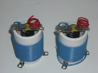
Just in case your are interesting I am selling a capacitor output kit in EBAy for the Dynaco 120. It is plug to plug compatible with the existing caps. Attached it is a picture and the link to EBAY.
Link to EBAY : http://my.ebay.com/ws/eBayISAPI.dll...ng&ssPageName=STRK:ME:LNLK:MESX&gbh=1&guest=1
Just in case your are interesting I am selling a capacitor output kit in EBAy for the Dynaco 120. It is plug to plug compatible with the existing caps. Attached it is a picture and the link to EBAY.
Link to EBAY : http://my.ebay.com/ws/eBayISAPI.dll...ng&ssPageName=STRK:ME:LNLK:MESX&gbh=1&guest=1
Attachments
Start by going to avahifi - Audio Basics Newsletter
Get the file 1984 Audio Basics and read pages pages 17-23.
A summary of the updates is below:
Q1 replace 40233 (100-250 beta) with BC108A (130-180 beta)
Q2 replace 2N3053 (100-200 beta) with 2N5320 (160-260 beta)
Q3 replace 2N3053 with TIP31C
Q4 replace 2N4037 with TIP32C
Q5, Q6 replace 2N3055 (17-25 beta) with 2N3772 (60-90 beta @ 1A)
D1 replace with 1N4733
D2,3 replace with 1N4004
C1 replace with 5 µF 10V tantalum
Add C13 68 pF from Q2C to Q2B, both channels
Add C14 0.01 µF from Q3C to GND, both channels
Add C15 27 pF from Q2C to Q1E, both channels
Add C16 .01 µF across xfmr secondary at rectifier bridge on PC-15
Replace C6 (30 µF, NP) with .47 µF Mylar
Add 3.3 Ohm ½ watt emitter resistor to Q4, both channels
Add 1 kOhm ½ watt resistor across the red/black output jacks
Your amplifier may already have some of the updates. For C1 try to find a film capacitor that fits instead of tantalum.
I did all of these updates in 1996 but I used a 10uF 50v electrolytic for C1.
Soon to overhaul again and use 4.7uF 250v polypropylene cap for C!.
I found fairchild TIP31/32c as drivers to be lacking in highs. the 40409 and 40410 that survive on the other side sound much better. I replace the TIP31/32c with MJE15028/29 and the sound is equal now. My hearing goes to 14 khz, most men can't tell the difference because of deafness.
What wattage are you running? I tried to use it as a 10 w/ch PA amp and the output transistors shorted again. set fire to the base stopper resistors (required on 4 mhz ft output transistor). I've added extra to3 heat sinks to the output transistor flanges and put a PCAT fan blowing on each one. That has made it survive thousands of hours in home (1/8 w base level, 70 W peak) use.
Mine has the djoffe bias control mod on the original PC15 side, and since the PC15 was so damaged on the other side, an AX6 over there. Very nice sound, and with it located behind an organ with the speakers on stands overhead projecting the highs down at my head, the fans aren't audible.
Last edited:
"put a PCAT fan blowing on each"
As in a 12v, 2" x 2" muffin fan?
powered by 9v dc, these should run quiet.
As in a 12v, 2" x 2" muffin fan?
powered by 9v dc, these should run quiet.
Can anyone recommend which transistors to use for PC-14 in the power supply?
Q7 was 2N4037, Q8 was 2N5320, and Q9 was 2N4347.
I have seen:
Q9 replaced by 2N3442,
Q8 replaced by TIP31C,
Q7 replaced by 2N4036.
I'm thinking of using:
MJ15003 for Q9, larger SOA... mounted on a large HS
MJE155028 for Q8, larger SOA
ECG323 for Q7, higher voltage TO-39... (maybe MJE15029)
I have read D. Joffe's "Circuit Description for the Dynaco Stereo 120 Power Supply".
It describes the current limit in Amps is about:
[β (Q8)] x [β (Q9)] x 0.0014 ≈ 120⋅37.5⋅0.0014 = 6.3Amps maximum.
That depends on the [hfe of Q8] x [hfe of Q9] x [Q8 base current].
Can anyone recommend which transistors to use for PC-14 in the power supply?
Q7 was 2N4037, Q8 was 2N5320, and Q9 was 2N4347.
I have seen:
Q9 replaced by 2N3442,
Q8 replaced by TIP31C,
Q7 replaced by 2N4036.
I'm thinking of using:
MJ15003 for Q9, larger SOA... mounted on a large HS
MJE155028 for Q8, larger SOA
ECG323 for Q7, higher voltage TO-39... (maybe MJE15029)
I have read D. Joffe's "Circuit Description for the Dynaco Stereo 120 Power Supply".
It describes the current limit in Amps is about:
[β (Q8)] x [β (Q9)] x 0.0014 ≈ 120⋅37.5⋅0.0014 = 6.3Amps maximum.
That depends on the [hfe of Q8] x [hfe of Q9] x [Q8 base current].
MJE155028 for Q8
should read MJE15028
dynxco.com also has PCB's with complete parts kit for amp driversImproved Dynaco ST-120 PCB's ONLY NO Components
are available @ http://www.dynxco.com
Can anyone recommend which transistors to use for PC-14 in the power supply?
Q7 was 2N4037, Q8 was 2N5320, and Q9 was 2N4347.
I have seen:
Q9 replaced by 2N3442,
Q8 replaced by TIP31C,
Q7 replaced by 2N4036.
I'm thinking of using:
MJ15003 for Q9, larger SOA... mounted on a large HS
MJE155028 for Q8, larger SOA
ECG323 for Q7, higher voltage TO-39... (maybe MJE15029)
I have read D. Joffe's "Circuit Description for the Dynaco Stereo 120 Power Supply".
It describes the current limit in Amps is about:
[β (Q8)] x [β (Q9)] x 0.0014 ≈ 120⋅37.5⋅0.0014 = 6.3Amps maximum.
That depends on the [hfe of Q8] x [hfe of Q9] x [Q8 base current].
MJE155028 for Q8
should read MJE15028
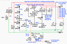
72volt regulator works great now... within 1/2% up to 3A and 1% up to 4.5A.... cuts current above 6A load.
I'm using:
Q7 = 2N3637 JAN
Q8 = TIP31C (100+ hfe)
Q9 = MJ15003G
Note that the regulator PCB has only 3 connections to the rest of the circuit.
Attachments
Last edited:
With a NET60 as Q9 and something TO220 I don't remember as Q8, my PC-14 was dropping the rail voltage at 3.5 amps load instead of 6.25 as originally designed. I concluded, perhaps incorrectly, that higher gain of modern transistors was messing up the performance.
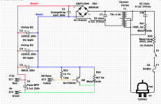
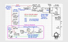
Replaced PC-14 with a point to point build of a zener 72 v stack driving 5 parallel TIP142 darlington regulators, to the original 3300 uf cap. Mounted the TIP142 on a Pentium2 heat sink. Replaced the current limit feature of the PC-14 with 10 A fuses to each PC-15. Have never blown a fuse.
With one 3300 uf rail cap driving both channels, I got 23.7 VAC out of both channels on 8 ohm speakers for 5 seconds on Rhianna Shut Up & Drive
70 watts per channel. I do have 2 PCAT fans and extra TO3 fins attached to the original heatsinks. The TO3 fins won't fit under the transistors.
Attachments

Last edited:
- Home
- Amplifiers
- Solid State
- Dynaco 120 Rebuild