Thanks Peter.
You can fit the driver into the line a lot ways. Motor depths and/or diameter are needed to sim it all accurately is all... Brian’s math equation estimators and workbooks seem to be good stuff from what I’ve seen and used myself in the past 🙂
You can fit the driver into the line a lot ways. Motor depths and/or diameter are needed to sim it all accurately is all... Brian’s math equation estimators and workbooks seem to be good stuff from what I’ve seen and used myself in the past 🙂
Just a brief update on the Silver Arches. I tried your trick of stuffing pillows in the line but this seemed to rob the life from the sub, so obviously it had become overstuffed.
It seems best with the 200mm pipes rolled in insulation and inserted into the 250 main pipe over the final two-thirds of the line. I have stuffed the smaller pipes with dacron-like filler.
It seems best with the 200mm pipes rolled in insulation and inserted into the 250 main pipe over the final two-thirds of the line. I have stuffed the smaller pipes with dacron-like filler.
You can’t stuff an overly short line. You must address the length issue no matter what. I might have mistyped or misread the question, but the length issue remains in any suggestions or ideas about the rss265 in these pipes you are using of any size. Stuffing is for fine tuning the damping not creating a false geometry by any huge margin
You have a driver with a resonant frequency of mid twenties in a pipe length for the 40s or so. It’s not tapered as an MLTL shape or anything so it’s just a (clogged up) pipe full of stuffing for a 40 hz tune and that’s what you’re hearing.
Think about that mid 20s Fs. It’s length of pipe needed, ‘5 pillows stuffed’ was a bit of sarcasm, sorry if that didn’t translate as such.
Think about that mid 20s Fs. It’s length of pipe needed, ‘5 pillows stuffed’ was a bit of sarcasm, sorry if that didn’t translate as such.
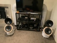
No, I did get to the 350cm line, by extending the pipe behind the TV, then putting another bend in, and then back down to the ground.
The ideal line length for that driver was around the 3.5m mark.
See image below
So can you make a few more bends in that or a partial loop shape that keeps the exit and driver radiating from a bit of distance?
Edit: I think I misread you? Is the pipe 350 long?
Last edited:
So can you make a few more bends in that or a partial loop shape that keeps the exit and driver radiating from a bit of distance?
How long is the pipe? 350cm? How big is the pipe? 438cm2.
Single driver in a 350 cm pipe
438cm2 = two big spikes at the ends of bandwidth with a saggy middle.
250cm2 = broad flat bandwidth.
Two drivers mounted beside each other at the same closed end in a 350 cm pipe
880 = two spikes and a saggy middle
438cm2 =broad flat bandwidth
250 cm2 = smooshed Low end appearing sealed box shaped response rolloff.
Last edited:
Yep, internal diam is 235 odd, so 438cm2 area roughly.
And yes, it is currently at 350cm in line length.
GM had said earlier: "FWIW, with damping he needs ~355 cm, so another 145 cm to get to the driver's ~20 Hz useful lower limit."
So do you think I could get a better/more even result with 248cm length (which is what one of the calcs actually said, though it doesn't get as low)?
If that's the case, I will simply make another one and have dual subs, with each finishing hidden in behind the TV.
You lost me? Or I dont understand what you’re saying?
Two things here: Line length and line area.
You can’t shorten one without screwing up the other there’s a damping you gotta satisfy too. Give and take or get funky response. You cannot shorten the line length without mass loading.
Vas and Q count !!! You Gotta keep the driver happy.
You have a 438cm2 pipe. This is way too huge for this drivers Q and Vas. It’s okay for (2) of those drivers together.
You need to simulate to see this or build a lot of transmissionlines(including mass loaded/bass reflex types). Horn response is your friend here.
My bad, I misinterpreted what you were saying.
So ideally I need to build a box that houses the two drivers and then insert the existing line into that.
And yes, I do need to get familiar with hornresp!
So ideally I need to build a box that houses the two drivers and then insert the existing line into that.
And yes, I do need to get familiar with hornresp!
My bad, I misinterpreted what you were saying.
So ideally I need to build a box that houses the two drivers and then insert the existing line into that.
And yes, I do need to get familiar with hornresp!
It’s not your fault, we both do (did)it, it’s like texting sucks, lol!
Yeah, look at Bjornes ‘hide away sub’ idea for a similar approach. A box and a hidden tube..
I wish someone had told me the trick about ditching the fence on my table saw (which was so wobbly and horrid that it was incapable of cutting a straight line; this was an old model prior to when they locked the fence at both ends!) and replacing it with a piece of 2x4 with a clamp at each end.
Now I'm more inspired to build a box to house both 10-inch drivers so it will load the pipe better. I just need to build up some confidence to construct a box with three holes. Guess it ain't that hard.
Could anyone suggest what the best location is for the two drivers? I'm thinking at opposing ends, so 180 degrees, as this will (to some extent?) cancel out vibrations that each sets up?
I note Pass didn't do it that way with his 18s in El-Pipo, with drivers at 90 degrees to each other rather than 180.
Is it better magnet out or driver out, or does it make absolutely no difference (in which case the box would look better with magnet in).
Google is your friend!: diy jigs for table saw - Google Search
There's all manner of DIY [power] tool adjustment, tuneup, jigs; for instance, this table saw sled: Table Saw Jigs: Build a Table Saw Sled
GM
There's all manner of DIY [power] tool adjustment, tuneup, jigs; for instance, this table saw sled: Table Saw Jigs: Build a Table Saw Sled
GM
Could anyone suggest what the best location is for the two drivers? I'm thinking at opposing ends, so 180 degrees, as this will (to some extent?) cancel out vibrations that each sets up?
I note Pass didn't do it that way with his 18s in El-Pipo, with drivers at 90 degrees to each other rather than 180.
Is it better magnet out or driver out, or does it make absolutely no difference (in which case the box would look better with magnet in).
Opposing with one driver reversed and wired backwards [in phase] to both cancel out rocking/coupling motion [vibration] and reducing 2nd harmonic distortion by averaging out any excursion misalignment.
They are [were?] 21" 😉 and still reduce vibration somewhat and apparently he was more interested in room coupling in the higher frequencies than complete cancellation.
GM
Here’s what we get: and red is with some stuffing added to the sim. Fs is 22.3hz, you can mess with the line shape and its length a bit and damp this as you prefer����. But for a plain no offset driver TL this is a great start to an easily tuned to taste subwoofer
Thanks for doing this sim on the RSS390HO.
Im thinking this might be a better driver for the 438cm2 line I already have that doesn't seem to work so well with one of the RSS265HOs.
I have an idea of how to implement this and was wondering whether your modelling had come up with this sized line - ie, 235mm internal diameter pipe - or whether it would be too narrow for this driver.
I understand the line is meant to be narrower than the driver for optimal results but is this too constricted?
And if not what length is recommended?
As an aside, I hooked up the other RSS265HO driver I had by dividing the line in two so each sub on each side was 250cm long. Not ideal, but talk about thunderous!
Only there seemed to be some frequencies it did well, and others not so much.
But Im getting items in the room that are vibrating at normal listening levels so two is better than one in terms of how it hits. The 350cm line with one RSS265 driver is probably better overall though, even if not ideal.
But if the RSS390HO works in the 438cm squared/235mm internal diameter pipe line that's where I'd like to head.
Cheers
Peter
It's not that it doesn't work so well as it requires much more stuffing to match the 2:1 CR pipe's performance and its fractional amount of stuffing in comparison.
Loading the 390 in the ~438 cm/355 cm pipe is a ~1.91:1 CR, so not enough difference to matter.
Yes, the pipe harmonic's dips are very audible, so for 'sub' duty you're limited to ~[2] octaves, i.e. the BW below its 3rd harmonic dip [1st and biggest one].
Note too that much of these are attenuated quite a bit if you sit at exactly the acoustic center point of an end loaded pipe's two ends.
GM
I made an easy 45.6cm2 (3” sced40 plastic pipe)plus rubber coupler( 40-83 cm2 in 4-5cm length) to adapt driver(rs100-8) to pipe so I could play with length, stuffing, pipe diameters from 86-46-22 and offset exit, and/or driver entry to compare the simmed results to measured and heard.
This was my way of learning what Greg is sharing generously. Thank you GM, this is a free head start����
What’s also part of my plastic pipe is a set of smooth bore 90 degree bends to bring the exit and driver ends together. Or lessen the ambiguous position of the ‘center’ to the simmed void or gap at the upper BW created in ‘path’ and offset driver or exit sims
That void is lessened by folding in sets of 3 in some cases more than others. I need to know this so I can use it in taped pipes with Rez chambers and similar ideas
Last edited:
Forgot to mention, the line won't be tapered; harder to do with big PVC pipe.
You don’t have to actually cut and bend the curcumfrebce of a pipe to obtain an acoustical shape or taper. You can insert solids to obtain occupied area in any transition or rate including various cheap pine 2x4 studs increasing in number toward the open end for mltl shape(taper) or opposite of that for an expansion or Hornlike shape wherecthe mouth size is bigger in CSA. Or full length to be a smaller CSA in a straight pipe
The damping thing done by the shape(taper/expand or a variety to tweak frequency response even more), the area/length for Fb with respect to Vas(large or small) from ~4x Vas total Vb, and stuffing or similar fibers in the path for certain parts affecting certain areas of bandwidth, or nearly anything depending on how it’s used(is it clogging up the line or helping as a filter of spikes in higher frequency?).
This stuff is making the box suite the Qes and Vas of the driver. Roll off and response peaks and valleys to which only the experienced like GREG actually know, as even HR sims are ambiguous, mostly when you make a complicated sim that’s compromised...as input data.
- Home
- Loudspeakers
- Subwoofers
- Quarter wave enclosure for Dayton RSS265HO-44?