What is the DC voltage on the terminals of Q952, from left to right?
1: 5.6v
2: -.03v
3: 5.58v
Voltages from Q951 and Q911?
Q951
1: 0v
2: 5.58v
3: 0v
Q911
1: 0v
2: 0v
3: 0v
Is the power switch on?
Fun fact. When I had originally pulled it apart, I checked for continuity across the switch. It showed good. Just checked the voltage. I was only getting like 2v on the output side. Reflowed the joint and now I'm getting power across the switch. Seeing as that was an issue, want me to recheck anything? I rechecked q911 since it was showing all 0v.
Also, even with the switch fixed, it still isn't turning on :/
Q911
1: 8.39v
2: 13.45v
3: 9.06v
Q952?
Q952
1: 5.77v
2: 5.77v
3: 0v
Also checked power draw as every time I touch the clip to my supply I get a tiny spark. Radio is pulling 258mA.
The spark is likely due to charging caps.
Do you have CE voltage at the microcontroller?
Yes. 5.3v
...I take it the microcontroller is dead?
It's possible.
Does it heat up?
Can you see any oscillation on the crystal terminals of the microcontroller?
Does it heat up?
Can you see any oscillation on the crystal terminals of the microcontroller?
It's possible.
Does it heat up?
Can you see any oscillation on the crystal terminals of the microcontroller?
Nope. Stays cool.
I take it I need to probe the am and fm vco pins with an oscilloscope? Or is there another crystal signal I need to check on the microcontroller?
X0 and X1 are the crystal terminals. Your probe will need to be set to 10x to limit the load on the crystal terminals. Even then, it could be too much of a load.
X0 and X1 are the crystal terminals. Your probe will need to be set to 10x to limit the load on the crystal terminals. Even then, it could be too much of a load.
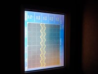
Well, even though it was faint, when checking x0 and x1 I could see a faint sine wave on the display of my scope.
At what frequency?
Hmm good question. My scope can't figure it out. I'd count the divisions and manually figure it out but I'm about to lay down for the night.
I realized I had my volts division too high and turned it down. Something tells me these aren't clean clock signals, though I haven't ever actually probed an oscillator before.
Just so I know I probed this right, I connect the probe ground to the radio ground, then check x0 and x1 individually, correct? Or, is x0 and x1 like positive and negative?
The pictures are of me probing it with the probe ground connected to the radio ground.
The "bigger" waveform is x0, and the smaller is x1.
Attachments
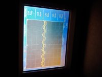
Set the scope to 1v/div and 10uS.
Here are the readings. The scope couldn't give a stable answer on the frequency. The pictures are just to show what the waveform looks like.
X0 big, x1 small
Attachments
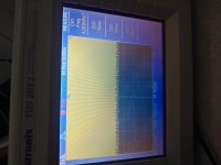
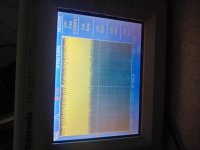
It looks like the oscillator is working.
Do you see any pulses on the outputs to the display board?
Do you see any pulses on the outputs to the display board?
It looks like the oscillator is working.
Do you see any pulses on the outputs to the display board?
(I'll check tonight when I'm at home)
What should I be looking for? Digital pulses? Or a constant digital high state (+5v?) vs digital low state (0v?)?
Also, how does the lcd get its power? Would it be reasonable to think that even if the microcontroller was dead, the backlight would at least turn on?
Also, I noticed the bulb for the radio buttons doesnt turn on. Assuming its not dead, how does it get its power? I know the schematic is really bad in that area...
- Home
- General Interest
- Car Audio
- Dead pioneer KE-1818?