An LCD display like this one doesn't really need any sort of supply. The segments are driven on'off by almost no current.
I can't see how the lamps are powered. It's often directly from the power switch but can be from transistors. They won't be powered by the microcontroller, directly.
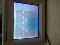
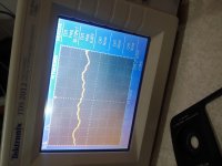
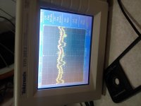
The pulses are typically 5v amplitude. I don't think you'll see any steady DC or ground.
I can't see how the lamps are powered. It's often directly from the power switch but can be from transistors. They won't be powered by the microcontroller, directly.
The pulses are typically 5v amplitude. I don't think you'll see any steady DC or ground.
An LCD display like this one doesn't really need any sort of supply. The segments are driven on'off by almost no current.
I can't see how the lamps are powered. It's often directly from the power switch but can be from transistors. They won't be powered by the microcontroller, directly.
The pulses are typically 5v amplitude. I don't think you'll see any steady DC or ground.
Well, I was about to say I think the display is bad cause the microcontroller is putting out good signals, but look at this. It's alive! But the backlight and button lights aren't working. I'm going to try and reflow the joints connecting the display and button board to the main pcb to see if that fixes it. If not, we'll have to keep digging.
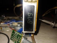
Edit: both backlights have power. Bad bulbs maybe?
I swear, if this was just a bad power switch and faulty bulbs, I'm going to be upset lol.
Attachments

Last edited:
The lamps don't last long. When I was doing warranty work, they sometimes failed within the 1 year warranty. I'd likely use LEDs with series resistors as replacements.
The lamps don't last long. When I was doing warranty work, they sometimes failed within the 1 year warranty. I'd likely use LEDs with series resistors as replacements.
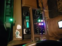
That's what I'm in the process of. I've got some green LEDs that'll match my interior lighting nicely, however they are a size bigger than the bulbs. The button led will be fine, but the back light led, ill prolly have to remove a smidge of material from the plastic behind the screen to make it work.
Attachments
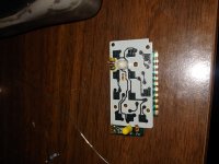
T-1 LEDS should fit.
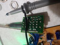
Welp, the saga continues. Zero sounds output. Not even a crackle or hum. I would presume the testing consists of at least testing to see if there's a signal getting to the output amp.
TA7280P
1: 1.44v
2: 1.44v
3: .01v
4: 1.43v
5: 1.44v
6: 6.56v
7: 6.73v
8: 12.64v
9: .01v
10: 13.45v
11: 12.62v
12: 6.68v
It appears pin 6 and 7 are a bit low, and I'm missing voltage at pin 9. Thoughts?
1: 1.44v
2: 1.44v
3: .01v
4: 1.43v
5: 1.44v
6: 6.56v
7: 6.73v
8: 12.64v
9: .01v
10: 13.45v
11: 12.62v
12: 6.68v
It appears pin 6 and 7 are a bit low, and I'm missing voltage at pin 9. Thoughts?
Something to note, the balance pot continuously spins. Prolly broke.... Could that be causing no sound to get through?
Do you have signal on terminals 1, 5, 7 and 12?
The DC bias point is 1/2 if the supply voltage.
9 is ground.
The DC bias point is 1/2 if the supply voltage.
9 is ground.
Do you have signal on terminals 1, 5, 7 and 12?
The DC bias point is 1/2 if the supply voltage.
9 is ground.
1 and 5 no signal, sitting at 1.5v.
7 and 12 do appear to be getting signal.
Attachments
Last edited:
Do you have it tuned to a station or have a cassette in the deck?
I have it tuned to a strong station. The signal lock symbol (the double rings I believe) is also on on the display.
Attachments
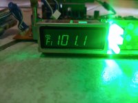
That's the stereo indicator.
Do you have audio on the non-grounded outer terminals of the volume control?
Do you have audio on the non-grounded outer terminals of the volume control?
That's the stereo indicator.
Do you have audio on the non-grounded outer terminals of the volume control?
Big signal is the two inside pins, small signal is outside pins.
Also, I can hear the music coming from... Something on the radio PCB with the volume turned up. Very faint, but I can make out acdc thunderstruck lol...
Attachments
The loudness terminal is on the board. It's generally off of the board. The terminals are ground, output, input and finally the loundess tap.
Does the input have good signal and the output vary with the volume control position?
Is the output making it to terminals 1 and 5 of the output IC?
Does the input have good signal and the output vary with the volume control position?
Is the output making it to terminals 1 and 5 of the output IC?
The loudness terminal is on the board. It's generally off of the board. The terminals are ground, output, input and finally the loundess tap.
Does the input have good signal and the output vary with the volume control position?
Is the output making it to terminals 1 and 5 of the output IC?
Man, this whole radio experience has made me feel real effin stupid.
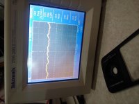
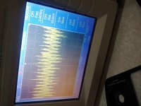
Just for giggles, I checked the output with my scope, and woah, there's an output signal! Then the gears started turning....pioneer didn't wire their stereos like they do today.
I assumed the green was speaker + and green/red was speaker - ... Nope. They grounded the speakers to the chassis and the green is FL and green/red is FR (not actually sure this orientation / color combo is correct). Soooo my wiring in my car is messed up. I hooked up a test speaker to the output and it works just fine. FML...
- Home
- General Interest
- Car Audio
- Dead pioneer KE-1818?