Hello--
Awhile back I picked up a pioneer ke-1818 from the junkyard to put in my old tercel. Finally got around to hackin out the fire hazard wiring harness the PO put together, modified my bezel, got it all hooked up, aaaaaand....nothin. Checked power at the plug, and it is getting power at the constant and switched 12v wires with the key on.
Alright. Took it apart, nothing looks obviously bad. Scrounged the interwebs and found a barely usable wiring diagram. Using it as a vague guide, I went to checking a few things.
I have power going across the switch.
Checking the brain chip (IC951, PD4275B) GND is good and I've got 5.2v at VDD1 and VDD2. I would assume VDD2 is outputting voltage based on the arrow.
What does CE mean on the chip? I'm curious since it has a voltage value next to it and I've got no power going to it.
Also, where is the chip getting its power from? Since there is +12v going to it from the BU line, I am curious what pin that is.
Where would it be logical to check next? To me it seems like the brains of this radio is dead :/
Attached the wiring diagram I am using.
Attachments
The 'brain chip' is referred to as a microcontroller.
CE is typically chip enable.
The service manual is available but it's not free.
If the controller is defective, is one available?
The microcontrollers of this vintage typically operated off of a 5v supply.
It may be less expensive to find a working model than it would be to repair this one.
CE is typically chip enable.
The service manual is available but it's not free.
If the controller is defective, is one available?
The microcontrollers of this vintage typically operated off of a 5v supply.
It may be less expensive to find a working model than it would be to repair this one.
The 'brain chip' is referred to as a microcontroller.
CE is typically chip enable.
The service manual is available but it's not free.
If the controller is defective, is one available?
The microcontrollers of this vintage typically operated off of a 5v supply.
It may be less expensive to find a working model than it would be to repair this one.
Eh, brain chip is easier to type than microcontroller 😛
If the chip isn't getting an enable voltage, maybe thats why it isnt working? What voltage is needed to enable the chip? 5v? If so, where can I source +5v to jumper to CE to see if thats the issue?
According to the schematic, CE is produced at the "IC951 power switch" at the output of DTA124ES--Q952. If there is no voltage there, what turns on Q952?
I picked up a KE-4444 to hopefully replace the ke-1818 in case its dead. Plus, the 4444 has RCA plugs for a sub amp. I made a post about the wiring cause I cannot find a manual for it anywhere.
It confuses those who are just learning to use terms that are made up.
Is D961 shorted?
No it isn't. With the black lead on the side with the line and the dmm in diode mode, I'm getting .722v, and with the leads reversed, no reading.
No reading? Does the meter shut off?
With the head unit powered up, what is the voltage across that diode?
With the head unit powered up, what is the voltage across that diode?
No reading? Does the meter shut off?
With the head unit powered up, what is the voltage across that diode?
It doesn't shut off. When the leads arent connected to a component, the screen says OL. With the leads in the incorrect orientation on the diode, the screen shows OL.
I will check the diode voltage tonight and report back.
OL is a reading. It means that the resistance is infinite or too high for the meter to read and it's significant.
No reading? Does the meter shut off?
With the head unit powered up, what is the voltage across that diode?
OL is a reading. It means that the resistance is infinite or too high for the meter to read and it's significant.
Gotcha. I will try to be more specific next time. What voltage should I be looking for across the diode?
With the head unit powered up, what is the voltage across that diode?
With the red lead on the squiggly line going across the triangle (don't know the technical name for it) and the black lead on the other, 5.6v
You only had to touch the probes to the two terminals of the diode. One is the anode. The other the cathode (stripe).
The diode is OK.
Can you get to the terminals of Q952?
The diode is OK.
Can you get to the terminals of Q952?
You only had to touch the probes to the two terminals of the diode. One is the anode. The other the cathode (stripe).
The diode is OK.
Can you get to the terminals of Q952?
Yes.
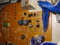
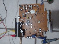
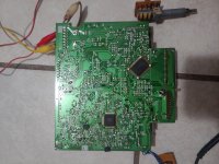
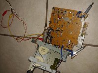
I've attached two pictures of the board and one of q952. The only thing unplugged from the circuit board is the tape deck. If the tape deck needs to be plugged in, let me know and I'll see what I can do.
Attachments
The cassette deck does need to be plugged in for some head units. Have you been doing all of this testing with it unplugged?
The cassette deck does need to be plugged in for some head units. Have you been doing all of this testing with it unplugged?
Yes. The wires on the cassette make it impractical to test most of the board. I plugged it back in and rechecked the diode. No change. Still outputting 5.6v
How do I go about testing q952?
The wires are generally long enough to allow you to twist the deck around and get to the board. Are they too short for that in this head unit?
The wires are generally long enough to allow you to twist the deck around and get to the board. Are they too short for that in this head unit?
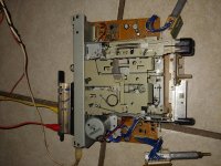
Ehhhh I can get it twisted like this after cutting a zip tie, but the possibility of the deck falling onto the board and shorting something out makes me nervous.
Attachments
Well, we tried. Maybe you can get the other deck working.
So... No reason for testing q952? If not, oh well. I'm hoping to find the output wiring for the other radio without having to take it apart to see the silk screen on the PCB.
You have to put some effort into this.
Would it be too difficult to get a piece of cardboard to keep the deck from shorting to anything?
Would it be too difficult to get a piece of cardboard to keep the deck from shorting to anything?
You have to put some effort into this.
Would it be too difficult to get a piece of cardboard to keep the deck from shorting to anything?
I apologise if something obvious to you may not be obvious to me :/
Yes, I can arrange something to prevent the deck from shorting to the deck.
- Home
- General Interest
- Car Audio
- Dead pioneer KE-1818?