Caution and note:
You Will blow up the amplifier if you ground the KT88 grids.
They need the fixed bias. Grounding them will redplate the KT88s.
You Will blow up the amplifier if you ground the KT88 grids.
They need the fixed bias. Grounding them will redplate the KT88s.
Yes, instead lift one end of both of the output tube grid coupling capacitors.
This leaves a proper DC bias path in place. Then if you still have the noise,
it is in the B+ or the output tubes.
This leaves a proper DC bias path in place. Then if you still have the noise,
it is in the B+ or the output tubes.
Last edited:
Terminate the 8 Ohm tap with 50 Watt power resistors.
Then connect large resistance series resistors from the 4 Ohm taps to your super sensitive headset.
You are using an amplifier that was designed to drive low efficiency loudspeakers in
a medium sized room, with acoustic losses.
You are miss-applying the same amp to drive a super high efficiency headset that has no acoustic losses.
@6A3sUMMER:
... and one more time, I do not use the amp as HPA, the headphones are only for checking noise performance. But again you are right with your statement.
@rayma
I hope you guys agree, I could probably lower some induced noise with a new bigger chassis to increase spacing between PT and OPT - which is quite an investment.
Adding the choke made an improvement, which indicates there is potential improvement at the B+, which after 2 pages brings me right back to post #1.
Still hoping for some votes whether and why choke or electronic choke/capacitance multiplier/gyrator or CCS + active regulation....
Actually it would trigger the protection relay in this particular amplifier, but you are right of course ... therefore ... see post #19Caution and note:
You Will blow up the amplifier if you ground the KT88 grids.
They need the fixed bias. Grounding them will redplate the KT88s.
... and one more time, I do not use the amp as HPA, the headphones are only for checking noise performance. But again you are right with your statement.
@rayma
Thank you, you are right, but I prefered to turn 4 trim-pots to the left 🙂Yes, instead lift one end of both of the output tube grid coupling capacitors.
I hope you guys agree, I could probably lower some induced noise with a new bigger chassis to increase spacing between PT and OPT - which is quite an investment.
Adding the choke made an improvement, which indicates there is potential improvement at the B+, which after 2 pages brings me right back to post #1.
Still hoping for some votes whether and why choke or electronic choke/capacitance multiplier/gyrator or CCS + active regulation....
rayma's post #22 suggestion to temporarily disconnect the coupling caps is the better way to 'divide and conquer' a hum/noise issue, as it retains the normal operating conditions of the output stage and allows a valid assessment of which stage the hum is originating in (assuming you can take before and after benchmark measurements that have sufficient technical detail, such as from a frequency spectrum plot).
Hum originating from an output stage can come from the bias supply, as well as the B+ supply, and from other forms of coupling or quirks.
Changing the bias voltage levels by trim pot adjustment is not a recommended diagnostic path to take, as it changes many operating conditions in the output stage.
Until you pursue a basic assessment of hum origin, including checking and appreciating how hum ingress can originate from grounding connections and poor wiring and layout interactions, then cherry-picking solutions that you think may work has a high risk of existing hum mechanisms remaining whist making ad-hoc modifications to circuitry and chassis that often end up just confusing the total picture.
Last edited:
@trobbins
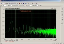
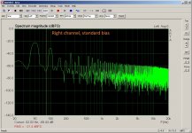
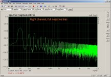
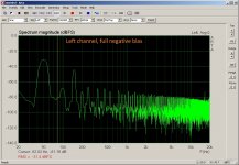
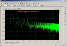
I hope I did this correct: I turned the gain of the soundcard full up (during the measurements it was showing always a green led, never went red). The measurements are NOT calibrated, please forget about the absolute numbers. I did not change any measuring setting, therefore relative numbers should tell something.
1) measurement: shortened probe to set the base line
2) measurement: left + right channel with maximum negative bias for the KT88s
3) measurement: left + right channel with standard bias for the KT88s
4) measurement: pulled the KT88s from left channel and removed grid caps from KT88s on right channel.
Please tell me what else I should try or measure.
Do you have a link to a good tutorial how to troubleshoot an amp ?
Thanks a lot for pointing that out to me, I didn't think enough !rayma's post #22 suggestion to temporarily disconnect the coupling caps is the better way to 'divide and conquer' a hum/noise issue, as it retains the normal operating conditions of the output stage and allows a valid assessment of which stage the hum is originating in (assuming you can take before and after benchmark measurements that have sufficient technical detail, such as from a frequency spectrum plot).
I hope I did this correct: I turned the gain of the soundcard full up (during the measurements it was showing always a green led, never went red). The measurements are NOT calibrated, please forget about the absolute numbers. I did not change any measuring setting, therefore relative numbers should tell something.
1) measurement: shortened probe to set the base line
2) measurement: left + right channel with maximum negative bias for the KT88s
3) measurement: left + right channel with standard bias for the KT88s
4) measurement: pulled the KT88s from left channel and removed grid caps from KT88s on right channel.
Please tell me what else I should try or measure.
Do you have a link to a good tutorial how to troubleshoot an amp ?
Attachments
-
 probe shortened.jpg188.1 KB · Views: 157
 -
 Right_4R_input_shortened_standard bias_no grid caps.jpg191.6 KB · Views: 61
 -
 Left_4R_input_shortened_no KT88s.jpg205.1 KB · Views: 62
 -
 Right_4R_input_shortened_standard bias.jpg191.5 KB · Views: 136
 -
 Left_4R_input_shortened_standard bias.jpg189 KB · Views: 156
 -
 Right_4R_input_shortened_full negative bias.jpg193.3 KB · Views: 165
 -
 Left_4R_input_shortened_full negative bias.jpg191.8 KB · Views: 154
My 2c worth.
Why does the bias diode bridge have caps across two diodes? What diodes are you using?
What happens if you replace the bias supply transistor regulator with a resistor dropper to a 100uF for each channel's bias raw supply?
Why are you using a 120k grid stopper for KT88's? Is that related to the anode to grid feedback? What happens if you disconnect the feedback and drop the stopper to 1k ?
C7, C15, C16 and C17 short HF to GND as do C6, C18. The diodes are UF4007 for bias and UF5408 for HV.My 2c worth.
Why does the bias diode bridge have caps across two diodes? What diodes are you using?
Should I add a snubber 1k + 1nF across the secondary of bias and HV ?
Simulation claims 8k2 + 100µF is five times better than transistor - will try in real 😀 thank you !What happens if you replace the bias supply transistor regulator with a resistor dropper to a 100uF for each channel's bias raw supply?
Yes.Why are you using a 120k grid stopper for KT88's? Is that related to the anode to grid feedback?
I loose all the goodies of the feedback - explained earlier - and gain absolutely nothing in terms of noise.What happens if you disconnect the feedback and drop the stopper to 1k ?
Attachments

alujoe2,
Using capacitors across diodes in a bias supply does not always reduce the noise of the supply.
Not when those high frequencies are now sent to "ground", it can cause ground loops.
The key is What ground loops you create, and how Localized they are.
As an example of what not to do:
Do not connect the center tap of a B+ secondary to a central ground, when that central ground also includes the RCA input connector returns, or even includes the cathode circuit of the input stage.
Instead, connect the center tap of a B+ secondary to the negative of the First B+ filter cap.
If instead, you use a bridge rectifier for the B+, then connect the negative of the bridge to the negative of the first filter cap.
Only after you have done this, then use a 2nd wire to connect fro the negative of the first filter cap, to the negative of the second B+ filter cap.
Now, use a 3rd wire to connect from the negative of the second B+ filter cap, to the central ground.
I hope you can see the way the transient currents of the first filter cap, and of the second filter cap, are dealt with Locally, Before you then connect to the central ground.
Schematics can not show you this, nor teach you this.
A few milli-Ohms of wire resistance that has 100s of milliamps of high frequency transient charging currents passing through them, develops enough voltage to disturb the sensitive inputs and sensitive input tube(s), if you connect the B+ minus directly to the central ground without localizing those current returns before they go to the central ground.
And, at about 10nH/inch, the inductance of those ground wires also develop a voltage across them due to the high frequency of the B+ rectifier / capacitor currents, versus the inductive reactance of the wire.
"Grounds are Commonly Misunderstood" - me
Some are not "grounded" in their theory.
Last edited:
I had never thought of it that way before, but what you said makes a LOT of sense to me. Akin to London Power's "galactic grounding" scheme.A few milli-Ohms of wire resistance that has 100s of milliamps of high frequency transient charging currents passing through them, develops enough voltage to disturb the sensitive inputs and sensitive input tube(s), if you connect the B+ minus directly to the central ground without localizing those current returns before they go to the central ground. And, at about 10nH/inch, the inductance of those ground wires also develop a voltage across them due to the high frequency of the B+ rectifier / capacitor currents, versus the inductive reactance of the wire."Grounds are Commonly Misunderstood" - me. Some are not "grounded" in their theory.
In addition to 6A3sUMMER excellent description, if you think there may be noise on the bias winding itself then that is better managed with a snubber directly across the winding to keep any such noise local to the winding (rather than lengthening the remediation circuts path to include a local ground connection). I suggest there would be no noticeable noise, especially if you are using UF4007, and you would be unlikely to have the test tools to confirm that one way or the other. I would also suggest that using ad hoc snubber values is poor design - if you were really concerned and have the test equipment to progress this topic then have a good long look at the Quasi-modo threads on this forum.
For faultfinding, I would suggest you test your theory that removing the anode-grid feedback and dropping the 120k stopper to 1k, actually does nothing for hum improvement when just looking at hum from the output stage (as per your test iterations in post #26).
For faultfinding, I would suggest you test your theory that removing the anode-grid feedback and dropping the 120k stopper to 1k, actually does nothing for hum improvement when just looking at hum from the output stage (as per your test iterations in post #26).
In post #26, can you confirm the input signal to the soundcard was achieved by connecting an unbalanced input lead to your amplifier's speaker output terminals, but for this particular test (1) you connected the input lead 'signal' wire to the speaker ground terminal rather than to the speaker output terminal ?1) measurement: shortened probe to set the base line
That benchmark configuration should then include any background noise/hum from the input lead going over to your amp, as well as any ground/earth loop involving the mains AC that powers your amp as well as your PC/soundcard.
alujoe2,
Using capacitors across diodes in a bias supply does not always reduce the noise of the supply.
Not when those high frequencies are now sent to "ground", it can cause ground loops.
The key is What ground loops you create, and how Localized they are.
As an example of what not to do:
Do not connect the center tap of a B+ secondary to a central ground, when that central ground also includes the RCA input connector returns, or even includes the cathode circuit of the input stage.
Instead, connect the center tap of a B+ secondary to the negative of the First B+ filter cap.
If instead, you use a bridge rectifier for the B+, then connect the negative of the bridge to the negative of the first filter cap.
Only after you have done this, then use a 2nd wire to connect fro the negative of the first filter cap, to the negative of the second B+ filter cap.
Now, use a 3rd wire to connect from the negative of the second B+ filter cap, to the central ground.
I hope you can see the way the transient currents of the first filter cap, and of the second filter cap, are dealt with Locally, Before you then connect to the central ground.
Schematics can not show you this, nor teach you this.
A few milli-Ohms of wire resistance that has 100s of milliamps of high frequency transient charging currents passing through them, develops enough voltage to disturb the sensitive inputs and sensitive input tube(s), if you connect the B+ minus directly to the central ground without localizing those current returns before they go to the central ground.
And, at about 10nH/inch, the inductance of those ground wires also develop a voltage across them due to the high frequency of the B+ rectifier / capacitor currents, versus the inductive reactance of the wire.
"Grounds are Commonly Misunderstood" - me
Some are not "grounded" in their theory.
Thank you for your reply, English is not my native tongue, I am confused now. I am convinced you are 100% correct, but I believe I did everything as you explained as C8 and C14 are attached to the 0 V reference (the schematic shows more or less the real thing).
If C6,C7, C15 is correct, why is C16-C18 wrong ? Please tell me in more detail what I did wrong.
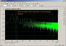
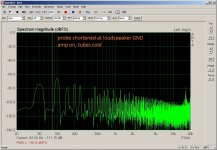
Attached are some more measurements. The amp has on the left channel the local feedback and on the right channel no local feedback with 1k grid resistor. I removed the 3 caps C16, C17 and C18 from the bias supply. One 4R from left channel 4 Ohm tab to GND and another 4R from right to GND.
1) I attached both alligator clips of the probe to the GND terminal of the loudspeaker terminals for the first measurement. The mains cable is not plugged in.
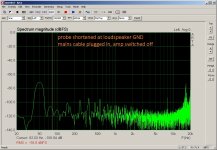
2) Mains cable plugged in, amp switched off.
3) Amp switched on, tubes cold.
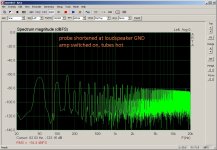
4) Tubes hot, still shortened probe at GND terminal.
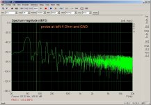
5) Probe at left 4 Ohm tab (and GND).
6) Probe at right 4 Ohm tab.
7) The old measurement with the C16-C18 in place.
What do you guys think ?
Attachments
-
 #6_probe right.jpg192.4 KB · Views: 46
 -
 #5_probe left.jpg189.2 KB · Views: 123
 -
 #4_probe shortened at loudspeaker GND - amp switched on, tubes hot.jpg201.1 KB · Views: 129
 -
 #3_probe shortened at loudspeaker GND - amp switched on, tubes cold.jpg199.1 KB · Views: 124
 -
 #2_probe shortened at loudspeaker GND - mains cable plugged in, amp off.jpg197.6 KB · Views: 127
 -
 #1_probe shortened at loudspeaker GND- no mains.jpg186 KB · Views: 134
 -
 Left_4R_input_shortened_standard bias.jpg189 KB · Views: 45
I am sorry, I don't understand what I am supposed to do, could you please be more specific ? To me the #28 measurement looks identical to the 'Right channel, standard bias' of post #26, what am I missing ?For faultfinding, I would suggest you test your theory that removing the anode-grid feedback and dropping the 120k stopper to 1k, actually does nothing for hum improvement when just looking at hum from the output stage (as per your test iterations in post #26).
Regarding your post #32: I am sorry, that was a mistake, I only shortened the two alligator clips and didn't attach them to anything. The result is worthless, as I can show more or less any noise level depending where I position the probe.
In addition to 6A3sUMMER excellent description, if you think there may be noise on the bias winding itself then that is better managed with a snubber directly across the winding to keep any such noise local to the winding (rather than lengthening the remediation circuts path to include a local ground connection). I suggest there would be no noticeable noise, especially if you are using UF4007, and you would be unlikely to have the test tools to confirm that one way or the other. I would also suggest that using ad hoc snubber values is poor design - if you were really concerned and have the test equipment to progress this topic then have a good long look at the Quasi-modo threads on this forum.
Thanks a lot for your reply !
I got the 1k + 1nF suggestion from "Rectifier snubbing - background and Best Practices", Morgan Jones, Linear Audio Volume 5, April 2013, pp. 7 - 26.I would also suggest that using ad hoc snubber values is poor design...
In "Soft Recovery Diodes Lower Transformer Ringing by 10-20X", Linear Audio Volume 10, Mark Johnson uses a C || C+R setup.
It is very easy to implement, therefore I just tried it 🙂.
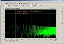
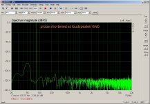
Amp has now local feedback on both channels again and 1k + 1nF across the bias secondary:
1) I attached both alligator clips of the probe to the GND terminal of the loudspeaker terminals for the first measurement. The mains cable is not plugged in.
2) Mains cable plugged in, amp switched off.
3) Amp switched on, tubes cold.
4) Tubes hot, still shortened probe at GND terminal.
5) Probe at right 4 Ohm tab (and GND).
6) Probe at left 4 Ohm tab.
What do you guys think ?
Attachments
-
 #06_1k+1nF probe shortened at loudspeaker GND, left 4Ohm.jpg188 KB · Views: 47
 -
 #05_1k+1nF probe shortened at loudspeaker GND, right 4Ohm.jpg190 KB · Views: 54
 -
 #04_1k+1nF probe shortened at loudspeaker GND, tubes hot.jpg200 KB · Views: 52
 -
 #03_1k+1nF probe shortened at loudspeaker GND, amp on, tubes cold.jpg198.3 KB · Views: 46
 -
 #02_1k+1nF probe shortened at loudspeaker GND, mains plugged in, amp off.jpg189 KB · Views: 43
 -
 #01_1k+1nF probe shortened at loudspeaker GND.jpg180.4 KB · Views: 48
C6, C7, C15 are not required - they appear to also be copied in to your schematic (like C16-C18) because I assume you have seen them in another schematic? Imho there is no benefit in adding them, and there can sometimes be a detriment. There has often been a perception that paralleling a big capacitor with a small capacitor provides better suppression of higher frequency noise - that situation is typically not valid for valve amps and modern parts and commonly used layouts.
It's good to see the benchmark plots for background noise/hum. There is nothing bad about having a noticeable level of background hum in a plot, as long as it is significantly below levels that you want to investigate (which it is), and as long as you have a good awareness of that background level.
I have a good USB soundcard, but it isn't perfect, so I have to know what options I have to make it better and apply them when I need to. Options I have available are to battery power the soundcard, to include a USB isolator, to use a battery powered laptop to run the software, and even to change soundcard channels as the left channel has some high frequency signals from within the soundcard that are well known but I know they are there and they don't impose on 95% of my testing).
So those background plots show that you don't have any quirky measurement setup issue when assessing the amp when it is on.
Are you able to confirm that both channels give close to the same hum levels when they are configured the same? If so, then the local feedback and stopper is mostly lowering hum and noise. But I would view that as a need to understand what is contributing the hum for starters, and using your measurement set up to make single changes and do comparisons to see if there is any one dominant contributor to the hum signals, and then return the local feedback setup later once you are satisfied that you have adequately suppressed all identifiable hum sources.
PS. I just noticed that you had posted again.
Last edited:
Yes, I just added them to see if anything improves. You know, the gurus talk, the fools (=me) try to make the best from the often opposing directions that are given. Your answer helps a lot !!!C6, C7, C15 are not required - they appear to also be copied in to your schematic (like C16-C18) because I assume you have seen them in another schematic? Imho there is no benefit in adding them, and there can sometimes be a detriment. There has often been a perception that paralleling a big capacitor with a small capacitor provides better suppression of higher frequency noise - that situation is typically not valid for valve amps and modern parts and commonly used layouts.
I think they are very similar, taking into account that the left channel has 6N(H)6P as driver, right channel uses a ECC99 (more gain, different THD). As the FFT is always fluctating, I didn't feel the need to replace the ECC99 with a 6N6P to get better results, but if you want it, I can do that, no problem.Are you able to confirm that both channels give close to the same hum levels when they are configured the same?
O.k. now I understand, makes a lot of sense. Thank you very much again !If so, then the local feedback and stopper is mostly lowering hum and noise. But I would view that as a need to understand what is contributing the hum for starters, and using your measurement set up to make single changes and do comparisons to see if there is any one dominant contributor to the hum signals, and then return the local feedback setup later once you are satisfied that you have adequately suppressed all identifiable hum sources.
My impression is that the hum/noise is proportional to the current drawn, therefore I was asking in post #1 for choke vs. active regulation.
I tried your suggestion regarding the bias supply. Because of the lack of real estate I settled in the moment for a one cap per channel solution. Do you think it is necessary to have one cap per tube in a PP amp ?
If so, please tell me and I will try to squeeze them in.
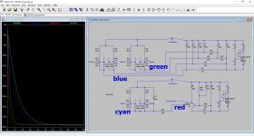
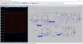
I am a little bit concerned regarding the start up time of RCRC or RCRCRC solutions (what happens if the amp is switched on again with tubes still hot, but bias at 0 ?). I did some simulation and decided to build the 'cyan' version after comparing start up time and ripple. Will post the measurements tomorrow.
Attachments
There are various time constants in an amp, so looking at just one TC may not provide a valid view. If your simulation is reasonably valid, then try and use it to identify a surge in cathode current in the output stage. One TC to consider would be the plate to B+ inductance, and how the series path resistance changes (ie. plate winding ESR, and increasing plate resistance of the valve plate characteristics if the operating loci starts off at 0V,0A and initially rises on the Vgk=0 curve).
For test purposes, temporarily adding in additional bias voltage smoothing capacitance should be relatively easy, as the extra capacitance can just be a flying part.
For test purposes, temporarily adding in additional bias voltage smoothing capacitance should be relatively easy, as the extra capacitance can just be a flying part.
Last edited:
Here are some measurements with the new bias supply ('cyan' version in post #36). In the sim the ripple was reduced a lot ('red' is original ripple). In addition the new RC for every channel is now at the amp board very close to the two trim-pots, the 'old' regulator is still on the supply board. Sadly I can't see an improvement.
@trobbins:
There is no difference wether the laptop runs from the mains or from the battery (the USB soundcard is still mains powered). Is more or less any USB isolator good enough, or do I need something guru approved ?
Do you think I should try something like this:
Looking for simple Push-Pull tricks (from Baby Huey) #1
Attachments

Are those 2 plots with the coupling cap to the output stage disconnected?
If the USB soundcard is mains powered then there is a chance of hum currents circulating around through the amp's earth and back to the soundcard. A USB isolator won't help that situation. Does the USB soundcard have a DC input port?
If the USB soundcard is mains powered then there is a chance of hum currents circulating around through the amp's earth and back to the soundcard. A USB isolator won't help that situation. Does the USB soundcard have a DC input port?
Sorry, no, I forgot to add the description. The amp was in working condition- wanted to here some music - that means, both channels with local feedback and coupling caps connected. Do you want me to repeat it with disconnected caps ?Are those 2 plots with the coupling cap to the output stage disconnected?
Yes the USB Soundcard uses a SMPS and has a 12V DC input, I have a battery, I don't yet have a plug that fits.If the USB soundcard is mains powered then there is a chance of hum currents circulating around through the amp's earth and back to the soundcard. A USB isolator won't help that situation. Does the USB soundcard have a DC input port?
Circulating hum currents have been a fact, I needed the Hum Bucking Resistor R26 and the diode bridge to PE to make it work, but it was a high pitched tone from the laptop (no disturbing sound in battery mode).
I removed the local feedback at the right channel (1k || to 120k and opened the 2M2, grid coupling caps connected). I tried to measure (inputs shortened), but it is very hard as the voltage readings are disturbed by random bursts.
For example the DMM tells me minimum 1 mVrms on the right channel 8 Ohm tab with random bursts up to maybe 20-30 mVrms (guessing from the bar). The left channel (feedback) shows 0.5 mVrms and way less frequent random bursts up to 5 mVrms. The DMM tells me about double the values on the loudspeaker terminals without the choke.
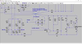
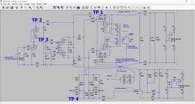
I borrowed an old analog 30MHz scope (the Tektronix TDS2012 didn't work very well). The scope shows about 800 mVpp at TP 1 (see attachment) with the choke L6 shortened and about 50 mVpp with the choke in action.
At TP2 - TP4 I cannot see any AC on the scope trace using the 5mV setting and a 1:10 probe. There are these random bursts, that make the trace jump up and down at all TPs.
As the active load on top of the input tube creates a voltage divider it is easy to see the relation ship between TP2 and TP3 by setting the TP2 probe to 10mV and TP3 to 5mV. Both traces are absolut identical in the bursts. Keeping TP3 and using TP1 for comparison, the TP3 follows the TP1 bursts. There is the delay during the step response, but it catches up soon. The TP4 seems to have the same problem, but to a much lesser degree, that is - absolutely no signs of AC, but small random bursts ('slower steps' than the HV).
The power transformer has about 60° C after 3 hours. Should I try an external TX for the filaments to ease the load on the PT ?
Do you want me to repeat the test with disconnected caps ?
What else should I try ?
Attachments
- Home
- Amplifiers
- Tubes / Valves
- How can I reduce hum/noise in KT 88 PP amp?