Hello! I could use some advice:
I am looking for a nice and simple solution for driving an 833a tube for audio applications. I am adapting an existing design that was built for hard switching via MOSFET driving. My goal here is to flip a switch to swap between PWM applications to audio amp applications.
What is the most minimal component driver design that can drive an 833a tube?
I am ok with solid state!
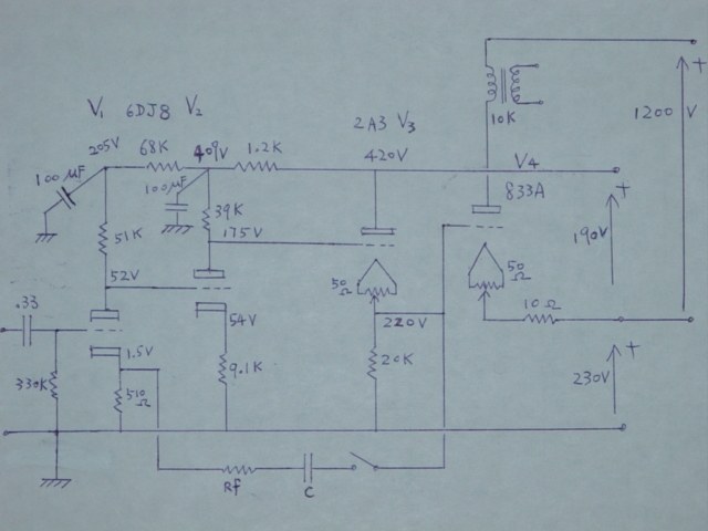
I can also get down with direct-drive tube drivers like this:
-Kyle
I am looking for a nice and simple solution for driving an 833a tube for audio applications. I am adapting an existing design that was built for hard switching via MOSFET driving. My goal here is to flip a switch to swap between PWM applications to audio amp applications.
What is the most minimal component driver design that can drive an 833a tube?
I am ok with solid state!
I can also get down with direct-drive tube drivers like this:
-Kyle
Attachments
I think all you need is 200vp-p drive at some suitably low impedance from a stage which runs a bit of current.
Source or cathode follower adds an additional stage, step down transformer adds requirement for greater drive to the primary, and probably additional gain stage up front.
For minimal parts, how about high mu triode loaded with CCS and take output from the 'mu' node for low drive impedance (couple hundred ohms). Something that sets up with a bit of current, 20mA say, D3A, with voltage gain around 65, that would work well. You could also try taking the output direct from the driver plate and see what works best for you. Single stage driver, no transformers, and you could find a way to direct couple the driver to the output grid using stacked supplies, or some other method. That driver stage could be as simple as two resistors, one tube, a CCS and a power supply.
HK
Last edited:
ah! That does sound simple! I have built a D3a headphone amp previously and found it to be a very simple and satisfying build.
Take a look at this screenshot:

Am I able to get away without a heat sync on these DN2540N5's?
I think a nice power supply for the 200v D3a stage could get away with something like this:
Regulator Power Supply board /Pcb / Kit DC200V+DC200V+DC12.6V For Tube Preamp | eBay
What do you mean(?):
Take a look at this screenshot:
Am I able to get away without a heat sync on these DN2540N5's?
I think a nice power supply for the 200v D3a stage could get away with something like this:
Regulator Power Supply board /Pcb / Kit DC200V+DC200V+DC12.6V For Tube Preamp | eBay
What do you mean(?):
a way to direct couple the driver to the output grid using stacked supplies, or some other method.
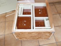
Tons of info here, 6 years since the build and sounding better than ever!
The Midlife Crisis - My 833C Amp Build
The Midlife Crisis - My 833C Amp Build
You need to figure out the 833 operating point that you would like to run, then work backwards from there to figure out what the requirements are for the cathode follower/fet follower directly coupled to the 833 grid.
Pay very, very, very close attention to peak grid current. At first glance when I saw that 2A3 cathode follower, my initial reaction was empathy for the hard life that the 2A3 would live in that position, but that depends on peak grid current.
Simple is such a relative term... Let's answer your question with a simple answer that's useless: run the tube in class A1.
With a plate voltage of just 2750V and a 10K output transformer, you can drive the 833 very easily and stay in class A1 to get about 50W of output. You need to drive the grid with 50V peak and deal with the miller capacitance of the 833, so a D3A should be fine, or even a 6HS5.
Not really useless, that's essentially what I'm doing in the Midlife Crisis. Class A1 to 40W or so, plate voltage 2300V. Class A2 up to nearly 200W.
Who wound you an OPT that will take 2kV plus the AC excursion?
Monolith Magnetics. Amorphous Metglas double C core, teflon interwinding insulation. The OPT weighs about 60lbs when potted.
Attachments


Last edited:
ah! That does sound simple! I have built a D3a headphone amp previously and found it to be a very simple and satisfying build.
Re: DN2540, I have had a hard time with keeping them from drifting, even with considerable sinks, in the end I abandoned them in favour of Gary Pimm CCS rev 5 (self bias), they are stable, present a higher impedance load, and more importantly sound better (immediately obvious). Something to do with avoiding non-linear input capacaties, I dont know for sure, just read it somewhere but they are clearly better (try the waybackmachine and search gary pimm rev5 CCS - easily built on perf board).
You can use the tube as you have in your schematic (I havent looked that closely at voltage etc but as a curosry view - no problems in general). From experience, I would take G3 to plate, 220R G2, G3 each to plate, current reg DC heater with 0.01uF from each pin to signal common, ferrite bead over each heater pin, 100R grid stopper for G1 with ferrite bead, again 'over the pin', 50R plate stopper, all CC resistors for those mentioned and include the cathode resistor with that.
If you replace the CCS with Pimm rev 5, you can take the output from the low impedance node (couple hundred ohm output drive impedance to the 833 grid), then you dont need the cathode bypass capacitor, as the Rk contribution to Rp of the stage is buffered by the SS output at the CCS. From experience, that would be my preference but be sure to try both configurations.
Easy to play around with, you're on the right track - go with it.
HK
Last edited:
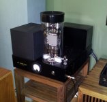
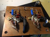
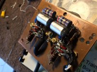
Fantastic build! Do you any fans inside or rely on convection?
Looks like there's a fan right under the tube.
Fantastic build! Do you any fans inside or rely on convection?
One Noctua fan under the 833, blowing up the chimney. Very quiet, can't hear it at all from my listening chair. It uses the pre-warmed air from inside the chassis to prevent over-cooling the 833. 6 years since the build and still working like a charm.
Thank you guys for your thoughts!
Hanze Khronye: I love the idea of the ultimate CCS! Ive been so conditioned to use big iron at the plates but rarely consider the solid state approach to the same activity. This time I am ready.. 😉
I managed to have found Garry Pimm's web page on the wayback machine.
Here is the newest member of the CCS family

As for the pentode wiring, was this what you meant? :

I suppose the parts where I get challenged are determining the values for R3 and adjusting R11.

Magz: Thank you for sharing your midlife crisis design. Looks quite simple in part count 🙂
I had one question which I have uploaded an image for visual aid:

I assume the suitable "adjustable shunt regulators" look like this below:
and the other question was about L2. Inductance? I am not familiar with having a coil as a grid leak resistor... what is the unit of that 540 value?
Hanze Khronye: I love the idea of the ultimate CCS! Ive been so conditioned to use big iron at the plates but rarely consider the solid state approach to the same activity. This time I am ready.. 😉
I managed to have found Garry Pimm's web page on the wayback machine.
Here is the newest member of the CCS family
As for the pentode wiring, was this what you meant? :
I suppose the parts where I get challenged are determining the values for R3 and adjusting R11.
This low impedance node, do you refer to the diagram on the right above? (where the pentode sits above?)If you replace the CCS with Pimm rev 5, you can take the output from the low impedance node (couple hundred ohm output drive impedance to the 833 grid), then you dont need the cathode bypass capacitor, as the Rk contribution to Rp of the stage is buffered by the SS output at the CCS. From experience, that would be my preference but be sure to try both configurations.
Is this what you meant?:current reg DC heater with 0.01uF from each pin to signal common, ferrite bead over each heater pin, 100R grid stopper for G1 with ferrite bead, again 'over the pin', 50R plate stopper, all CC resistors for those mentioned and include the cathode resistor with that.
Magz: Thank you for sharing your midlife crisis design. Looks quite simple in part count 🙂
I had one question which I have uploaded an image for visual aid:
I assume the suitable "adjustable shunt regulators" look like this below:
and the other question was about L2. Inductance? I am not familiar with having a coil as a grid leak resistor... what is the unit of that 540 value?
Yes, that is the CCS, the simpler one at the left hand side. The low impedance node is labelled 'mu' on the drawing. You really want a resistor from G3 to plate, the same as you have done for G2, and I'd add another between the plate and CCS as well (and dont forget G1).
With the heater arrangement, yes like that but I was referring to D3a (6.3V). Ground the centre spiggot of the socket and install radial leaded cap that fits between tube pin and centre spiggot with zero lead length. At the socket, use both cathode pins for Rk and 0.01 bypass Rk is a good idea as well. Keep grid and cathode circuit away from plate circuit..
With the heater arrangement, yes like that but I was referring to D3a (6.3V). Ground the centre spiggot of the socket and install radial leaded cap that fits between tube pin and centre spiggot with zero lead length. At the socket, use both cathode pins for Rk and 0.01 bypass Rk is a good idea as well. Keep grid and cathode circuit away from plate circuit..
Attachments

Last edited:


Ah oops! My previous schematic had the two filament capacitors tied not to signal ground. Now it is adjusted.

What does the potentiometer on the Pimm board do? What are the tuning procedures? I was having a little difficulty identifying the instructions on Gregg's Wayback machine page.
When compared to the MLC (Mid Life Crisis):
It would seem to me that this Greggs CCS board accomplishes the required regulated voltages internally.

I like the idea that the Pimm boards allow the elimination of cathode bypass capacitors &/or LED's in the signal path
What does the potentiometer on the Pimm board do? What are the tuning procedures? I was having a little difficulty identifying the instructions on Gregg's Wayback machine page.
When compared to the MLC (Mid Life Crisis):
It would seem to me that this Greggs CCS board accomplishes the required regulated voltages internally.
I like the idea that the Pimm boards allow the elimination of cathode bypass capacitors &/or LED's in the signal path
Careful with the bleeder resistor at the end of the HT: 2kV on a 1M resistor results in 4W dissipation.
Besides a power rating, resistors have a voltage rating as well. Respect that rating or it will flash over eventually.
You should put resistors across the stacked HT caps anyways to evenly distribute the voltage. They'll serve as bleeders as well, so no need for the 1M.
Also, you should consider DC on the filament of the 833: a high mu triode with 10V@10A will hum when heated on ac. Magz uses Coleman regs, ReinoutdV used LCLC (Where are the 833 amps?) .
The filament supply is an essential part of the design of an 833 amp.
Thanks @Parafeed813 for the note! I have yet to fully address the HT power supply side of things. These are important wattage and safety notes!
The Rod Coleman Regulators:
DHT filament regulator – Bartola(R) Valves
Rod Coleman DHT Filament Regulator
So using OTS meanwell 5V power supplies would be noticeably destructive to the signal?:
RS-35-5 - MEAN WELL - TRC Electronics
I love the idea of ready to go, small-lead-time, minimal installation/fus..
but if this introduces too much garbage on the signal, Rod-Coleman heaters look like the holy grail. I suppose I will contact him if he can assemble the circuits in his pricing 🙂
What does the potentiometer on the Pimm board do? What are the tuning procedures? I was having a little difficulty identifying the instructions on Gregg's Wayback machine page.
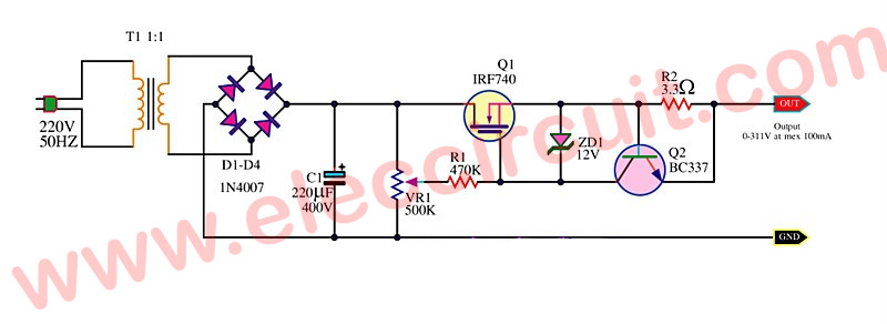
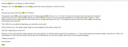
Pot allows for adjustment of current. Set up R1 in accordance with the following:
Attachments
- Home
- Amplifiers
- Tubes / Valves
- 833a Solid State Driving