This is my first post on an audio forum & will be my first Amplifier build. I hope there is someone out there in DiyAudio land that will have interest in this build and help me through this my first amplifier build.
Warning I know very little about electronics and will be asking lots of stupid questions, I have done some reading on the subject and was lost in the acronyms. I do hope to learn something during this build. Limit mistakes and not blow anything up.
Starting at Power Supply -
12L6 GT SE AMP to 6W6GT SE AMP
I read an Amp build article in audioXpress by Rick Spencer (Min Single Ended) using 2 x 12L6 and 1 x 12SN7. The design made 195V plate & 124V screen with clamed nearly 4 watts output.
Power Transformer
Power Transformer increasing voltage for 6W6GT
I am not sure how to work out the math increasing voltage for the 6W6 GT and ensure the screen voltage stays under the limiting factor 150V maximum screen voltage. The method I have used may be totally wrong. I have taken the percentage of voltage drop from the 12L6 / 12SN7 mini single ended design using power transformer (T1a) supply voltage and compared it to higher power supply voltages that can be used for the 6W6GT Maximum ratings 300V plate & 150V screen.
Power transformer used in 12L6/12SN7 Mini Single Ended
T1a - 215 Voltage Secondary
Hammond 261M6 (83VA) - Transformer used with schematic 12L6 GT SE AMP Min Single Ended
Primary Mains impute 115V 60 Hz (will not work on 230 Mains supply)
1st Secondary - 215V @ 296 mA
2nd Secondary 6.3V @ 4A
Posable power transformers that could be used with 6W6GT
T1b - 230 Voltage Secondary
AnTec - AS-1T230 - 100VA 230V TRANSFORMER
Primary Mains impute 115V or 230V at 50Hz or 60Hz
Power 100VA
Secondary Outputs 4x
1st Secondary- 230V @ 0.22A
2nd Secondary - 230V @ 0.22A
3rd Secondary - 6.3V @ 3A
4th Secondary- 6.3V @ 3A
T1c - 240 Voltage Secondary- “50VA Low”
AnTec -AS-05T240 - 50VA 240V TRANSFORMER
Primary Mains impute 115V or 230V at 50Hz or 60Hz
Power 50VA (The output voltage current is only 100 milliamps)
Outputs3x
1st Secondary - 240V @ 0.1A
2nd Secondary - 6.3V @ 2A
3rd Secondary - 6.3V @ 2A
T1d 250 Voltage Secondary
AnTec -- AS-1T250 - 100VA 250V TRANSFORMER
Primary Mains impute 115V or 230V at 50Hz or 60Hz
Power 100VA
Secondary Outputs 4x
1st Secondary- 250V @ 0.2A
2nd Secondary - 250V @ 0.2A
3rd Secondary - 6.3V @ 3A
4th Secondary- 6.3V @ 3A
AnTek power Transformers are inexpensive and provide input mains voltage for both 120VAC or 230VAC with ready stock available – I am moving to Indonesia soon and have limited time to purchase transformer before I go.
Calculating increasing voltage.
The method I have used may be totally wrong for calculating increasing voltage.
Screen Voltage
Screen Voltage (method may be totally wrong I am trying to learn)
Primary
Voltage Percentage of V drop Volt drop Final Screen voltage
T1a 215V X 0.423 = 90.95 215V - 90.95 = 124.5 Hammond
T1b 230V X 0.423 = 97.29 230V - 97.29 = 133.7 AnTek
T1c 240V X 0.423 = 101.52 240V - 101.52 = 138.48 AnTek
T1d 250V X 0.423 = 105.75 250V - 105.75 = 144.25 AnTek
Plate Voltage
Plate Voltage (method may be totally wrong I am trying to learn)
Primary
Voltage Percentage of V drop Volt drop Final Screen voltage
T1a 215V X 0.094 = 20.01 215V - 20.01 = 194.5 Hammond
T1b 230V X 0.094 = 21.62 230V - 21.62 = 208.38 AnTek
T1c 240V X 0.094 = 22.56 240V - 22.56 = 117.44 AnTek
T1d 250V X 0.094 = 23.5 250V - 23.5 = 226.5 AnTek
Output Wattage estimation
Method for estimating wattage increase may be totally wrong.
Averaging from data sheet 110V screen is 2.1watt and 200V screen is 3.8 watt gives (52.6 volt supply = 1 watt)
Supply Voltage = Plate voltage = Output watts Transformer Note
T1a 215 = 195 = 3.7 watts -no 230VAC Mains primary
T1b 230 = 208.4 = 3.9 watts AnTek – 100VA
T1c 240 = 217.0 = 4.1 watts AnTek – “50VA Low”
T1d 250 = 226.6 = 4.3 watts AnTek – 100VA
Heater (Filament) voltage 6.3V
Heater (Filament) Amps (current)
I believe tis is how to work out heater filament current?
6W6-GT Heater Current 1.2 Amperes x2
6SN7-GTB Heater Current 0.6 Amperes x1
Total heater current requirement 3A + 30% = 4A
Heater (Filament) 6.3V @ 4A ?
1st Secondary Transformer current Amperage requirement
I am an unsure where and how to obtain this requirement?
From the GE 6W6GT & 6SN7-GTB Data Sheet
6W6-GT MAXIMUM RATINGS
DC Cathode Current 60 Milliamperes
Peak Cathode Current 180 Milliamperes
6W6-GT CLASS A, AMPLIFIER CHARACTERISTICS AND TYPICAL OPERATION
Plate 200 Volts/ Screen 125 Volts
Zero-Signal Plate Current 46 Milliamperes
Maximum-Signal Plate Current 47 Milliamperes
Zero-Signal Screen Current 2.2 Milliamperes
Maximum-Signal Screen Current 8.5 Milliamperes
6SN7-GTB Class A Amplifier MAXIMUM RATINGS DESIGN-CENTER VALUES UNLESS OTHERWISE INDICATED, EACH SECTION
DC Cathode Current 20 Milliamperes
Peak Cathode Current 70 Milliamperes
Power Transformer Connection (Attached Drawing parallel wiring secondaries)
If transformer T1d was used.
I can wire together in parallel 1st Secondary & 2nd Secondary for 250V @ 0.4A
I can wire together in parallel 3rd Secondary & 4th Secondary for 6.3V @ 6A
My plan is to use basically the same schematic as the using 12L6/12SN7 Mini Single Ended schematic. Changing the vacuum tubes to 2 x 6W6 and 1 x 6SN7 and increase voltage to get a full 4 watts. With option to run amp on 120VAC or 230VAC mains supply (I move to different country’s often).
12L6GT = maximum rating 200V plate / 125V screen
6W6GT = maximum rating 300V plate / 150V screen
I believe using the 6W6GT 4+ Watts can be achieved with under 250 Volts on plate & under 150 Volts on screen using basically the same schematic.
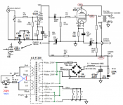
SEE Attached Schematic Mini Single Ended 12L6..12SN7
Warning I know very little about electronics and will be asking lots of stupid questions, I have done some reading on the subject and was lost in the acronyms. I do hope to learn something during this build. Limit mistakes and not blow anything up.
Starting at Power Supply -
12L6 GT SE AMP to 6W6GT SE AMP
I read an Amp build article in audioXpress by Rick Spencer (Min Single Ended) using 2 x 12L6 and 1 x 12SN7. The design made 195V plate & 124V screen with clamed nearly 4 watts output.
Power Transformer
Power Transformer increasing voltage for 6W6GT
I am not sure how to work out the math increasing voltage for the 6W6 GT and ensure the screen voltage stays under the limiting factor 150V maximum screen voltage. The method I have used may be totally wrong. I have taken the percentage of voltage drop from the 12L6 / 12SN7 mini single ended design using power transformer (T1a) supply voltage and compared it to higher power supply voltages that can be used for the 6W6GT Maximum ratings 300V plate & 150V screen.
Power transformer used in 12L6/12SN7 Mini Single Ended
T1a - 215 Voltage Secondary
Hammond 261M6 (83VA) - Transformer used with schematic 12L6 GT SE AMP Min Single Ended
Primary Mains impute 115V 60 Hz (will not work on 230 Mains supply)
1st Secondary - 215V @ 296 mA
2nd Secondary 6.3V @ 4A
Posable power transformers that could be used with 6W6GT
T1b - 230 Voltage Secondary
AnTec - AS-1T230 - 100VA 230V TRANSFORMER
Primary Mains impute 115V or 230V at 50Hz or 60Hz
Power 100VA
Secondary Outputs 4x
1st Secondary- 230V @ 0.22A
2nd Secondary - 230V @ 0.22A
3rd Secondary - 6.3V @ 3A
4th Secondary- 6.3V @ 3A
T1c - 240 Voltage Secondary- “50VA Low”
AnTec -AS-05T240 - 50VA 240V TRANSFORMER
Primary Mains impute 115V or 230V at 50Hz or 60Hz
Power 50VA (The output voltage current is only 100 milliamps)
Outputs3x
1st Secondary - 240V @ 0.1A
2nd Secondary - 6.3V @ 2A
3rd Secondary - 6.3V @ 2A
T1d 250 Voltage Secondary
AnTec -- AS-1T250 - 100VA 250V TRANSFORMER
Primary Mains impute 115V or 230V at 50Hz or 60Hz
Power 100VA
Secondary Outputs 4x
1st Secondary- 250V @ 0.2A
2nd Secondary - 250V @ 0.2A
3rd Secondary - 6.3V @ 3A
4th Secondary- 6.3V @ 3A
AnTek power Transformers are inexpensive and provide input mains voltage for both 120VAC or 230VAC with ready stock available – I am moving to Indonesia soon and have limited time to purchase transformer before I go.
Calculating increasing voltage.
The method I have used may be totally wrong for calculating increasing voltage.
Screen Voltage
Screen Voltage (method may be totally wrong I am trying to learn)
Primary
Voltage Percentage of V drop Volt drop Final Screen voltage
T1a 215V X 0.423 = 90.95 215V - 90.95 = 124.5 Hammond
T1b 230V X 0.423 = 97.29 230V - 97.29 = 133.7 AnTek
T1c 240V X 0.423 = 101.52 240V - 101.52 = 138.48 AnTek
T1d 250V X 0.423 = 105.75 250V - 105.75 = 144.25 AnTek
Plate Voltage
Plate Voltage (method may be totally wrong I am trying to learn)
Primary
Voltage Percentage of V drop Volt drop Final Screen voltage
T1a 215V X 0.094 = 20.01 215V - 20.01 = 194.5 Hammond
T1b 230V X 0.094 = 21.62 230V - 21.62 = 208.38 AnTek
T1c 240V X 0.094 = 22.56 240V - 22.56 = 117.44 AnTek
T1d 250V X 0.094 = 23.5 250V - 23.5 = 226.5 AnTek
Output Wattage estimation
Method for estimating wattage increase may be totally wrong.
Averaging from data sheet 110V screen is 2.1watt and 200V screen is 3.8 watt gives (52.6 volt supply = 1 watt)
Supply Voltage = Plate voltage = Output watts Transformer Note
T1a 215 = 195 = 3.7 watts -no 230VAC Mains primary
T1b 230 = 208.4 = 3.9 watts AnTek – 100VA
T1c 240 = 217.0 = 4.1 watts AnTek – “50VA Low”
T1d 250 = 226.6 = 4.3 watts AnTek – 100VA
Heater (Filament) voltage 6.3V
Heater (Filament) Amps (current)
I believe tis is how to work out heater filament current?
6W6-GT Heater Current 1.2 Amperes x2
6SN7-GTB Heater Current 0.6 Amperes x1
Total heater current requirement 3A + 30% = 4A
Heater (Filament) 6.3V @ 4A ?
1st Secondary Transformer current Amperage requirement
I am an unsure where and how to obtain this requirement?
From the GE 6W6GT & 6SN7-GTB Data Sheet
6W6-GT MAXIMUM RATINGS
DC Cathode Current 60 Milliamperes
Peak Cathode Current 180 Milliamperes
6W6-GT CLASS A, AMPLIFIER CHARACTERISTICS AND TYPICAL OPERATION
Plate 200 Volts/ Screen 125 Volts
Zero-Signal Plate Current 46 Milliamperes
Maximum-Signal Plate Current 47 Milliamperes
Zero-Signal Screen Current 2.2 Milliamperes
Maximum-Signal Screen Current 8.5 Milliamperes
6SN7-GTB Class A Amplifier MAXIMUM RATINGS DESIGN-CENTER VALUES UNLESS OTHERWISE INDICATED, EACH SECTION
DC Cathode Current 20 Milliamperes
Peak Cathode Current 70 Milliamperes
Power Transformer Connection (Attached Drawing parallel wiring secondaries)
If transformer T1d was used.
I can wire together in parallel 1st Secondary & 2nd Secondary for 250V @ 0.4A
I can wire together in parallel 3rd Secondary & 4th Secondary for 6.3V @ 6A
My plan is to use basically the same schematic as the using 12L6/12SN7 Mini Single Ended schematic. Changing the vacuum tubes to 2 x 6W6 and 1 x 6SN7 and increase voltage to get a full 4 watts. With option to run amp on 120VAC or 230VAC mains supply (I move to different country’s often).
12L6GT = maximum rating 200V plate / 125V screen
6W6GT = maximum rating 300V plate / 150V screen
I believe using the 6W6GT 4+ Watts can be achieved with under 250 Volts on plate & under 150 Volts on screen using basically the same schematic.
SEE Attached Schematic Mini Single Ended 12L6..12SN7
Attachments
Concur with both those points:
R7 must be meant to go to ground! Otherwise V2 melts its grid!
And yes the filament supply needs a regulator chip in either of two variants. The 6.3V secondary can't provide enough headroom for a regulator though, and is best used directly as AC for 6.3V heaters.
The 12.6V version gives 17V DC which is enough headroom to drive some 7812's
Ketje, Mark & pblix thanks for the replies really appreciate the help. I really need some help to accomplish this.
Power Transformer
My first goal is to get the power transformer will the AnTec - AS-1T250 - 100VA 250V TRANSFORMER work for what I would like to accomplish? I will leave the country moving to Bali as soon as borders open, be nice to have a decent stereo in Bali. Shipping transformer overseas will make it cost double.
Point 1 – R7 to Ground not Positive V2 pin 5
Please see attachment clarify how this should be grounded? Method A or B (R7 to ground Change schematic)
Thanks
Attachments
Filament supply (heater supply)
If the Filament supply is AC will this not add risk of hum?
Regulator chip sounds more complicated and more things to buy?
Headroom does that mean not enough voltage or amperage or both? Sorry I am trying to learn and will ask lots of stupid questions.
For 12.6V heaters I will have to buy a complete set of tubes? I have a couple 6W6 and 6SN7 tubes they where tested years ago and I bought 2 tested & matched 6W6GT tubes.
All advice appreciated you guys & gals are great
My 2 cents. I would spend more time on this schematic before buying parts for it. Couple of things you should consider beside the mistakes listed on previous posts are: Since you are designing from a new, you might consider a more efficient CLC filter instead. Also, this design uses a Pentode output stage without using negative feedback to lower distortion and output impedance. Unless you are building for none Hi-Fi purpose, I would spend more time to see if there are more suitable circuits. Also, the way it is configured, you will likely end up with less than 3W.
Alllensoncanon -thanks for the feedback greatly appreciated,
I understand the design is of critical importance– Filtering no hum I want to learn. There is not many schematics on amplifiers using the 6W6 power tube. There is a couple articles using 12L6, 6W6 and 6Y6 with 215V power transformer calming 3 watts evil science Audio 6W6 and this schematic using a 12L6 calming almost 4 watts. There is a bit of how good they sound and running them at 300V+ and a lot of planning on building a 6W6 Amp that does not materialize.
I have efficient speakers. I fell 4 watts is plenty for me. Like you suggest filters sound quality is important and I want to learn the why and how, also the acronyms but they are not as important to me. Taking on something that will be a bit of a challenge, so I can learn and share I think would be better than soldering a kit.
Big Items first,
I am moving overseas and 40 dollar transformer will end up costing over 100 dollars once I am overseas. If I could get the larger components that are not readily available first this would be a big +. Reality is it won’t happen if I do not get the big components first. Resisters capacitor are readily available transformers for tube amps not so. These things must be shipped, imported taxed and taxed again unless you have good connections. 10 dollars’ worth of tubes = 35 dollars to ship + customs looking at invoice of 45 dollars. Then try to charge another 30. So, a 10 dollar tube will now cost 85 dollars. I bargain and spend all day till I get them down, so I do not pay quite that much. Life is better when you are only missing the easy components.
I have tubes I have 4000-ohm SE output transformers just over 2lbs each, I am committed. But I will need help.
The circuit will not make 4 Watts per channel after the AC losses in the output transformer & DC voltage drop in the cathode resister & DC drop in the output transformer primary. The numbers printed for the tubes on their data sheets are all the ideal with no losses.
The audio power available will be more like 2.5-3 Watts,🙂
DC on the heaters is not a requirement for a power amplifier. Just another complication. The blue LED will need a limiting resister. Running on an AC heater supply their should be a reverse connected diode such as a 1N4007 in parallel with the LED.
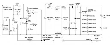
Hot Rodded AA5 12SQ7 50L6
I stuffed this into an old AA5 receiver several years ago. So more recently it became the subject of a presentation I did at the local Vintage Radio Club. It clips at a bit more than 2.5 Watts. Just another Feedback Pair, very similar to your project as far as the output tube & conditions are concerned. And apologies to those who already may have seen this on DIY recently.
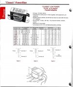
Hammond has a PT in their product line that would power both the filaments & B+ if they were for 6V heaters. Their 261M6, information attached.🙂
I stuffed this into an old AA5 receiver several years ago. So more recently it became the subject of a presentation I did at the local Vintage Radio Club. It clips at a bit more than 2.5 Watts. Just another Feedback Pair, very similar to your project as far as the output tube & conditions are concerned. And apologies to those who already may have seen this on DIY recently.
Hammond has a PT in their product line that would power both the filaments & B+ if they were for 6V heaters. Their 261M6, information attached.🙂
Attachments
Not so nice 🙁
Powered directly from the power line 😱
And a PP OPT in an SE amp 😕
Mona
All to true! But a challenge is a challenge, why not see what can be done at least cost. The radio was one of those very common in the later 30s & thru the 40's. North America was covered in them. Probably does meet the safety standards of today but does not claim to.
The Hammond 125D OPT replaced the much smaller OPT that the receiver came with. This modification was done at a time before Hammond introduced their modern SE line. The 125D was in my junk box, why not utilize it?
The net result was better than expected. I put it up here simply as another example of a feedback pair, similar to what is in this thread, So ignore the half-wave voltage doubler, OPT with no gap & direct connexion to the power line. It is what it is!!🙂
jhstewart9 - Thankyou this reconfirms the starting point
The Hammond 261M6 (83VA) – Transformer
Primary Mains impute 115V 60 Hz (will not work on 230 Mains supply)
1st Secondary - 215V @ 296 mA
2nd Secondary 6.3V @ 4A
Is what was used by Rick Spencer 12L6 (Min Single Ended)in a audioXpress article.
It also looks be the transformer used by evil science Audio in Low Voltage Single-Ended Madness 6W6 /6Y6 Amplifier
I an looking for a transformer that can be used to wit 120V & 230 Volt mains supply.
If you promote a line powered amplifier, then . . .
The surviving spouse may get good expensive lawyers to sue both you and this forum.
And, the surviving spouse will win.
Always preface any line powered amplifier with: "this works great, but it may kill you!"
Better yet, do not promote it at all.
This forum has lots of readers who do not know how dangerous what you are promoting is.
Cheap is not good if it kills.
All tube amps have potential to kill, but lets not play Russian Roulette with all 6 revolver spots loaded at the same time.
Last edited:
I'll bet more people died from the old curtain burners than the direct line. That being said there is also the misconception that a fuse will prevent electrocution. It won't. It's more of a second mouse gets the cheese solution for not using a transformer. As for safety caps aren't they internally fused? Is that what makes them a "safety cap"? At least they wont start a fire?
6A3sUMMER - I believe you have mis-understood, I believe he is promoting a Hammond power transformer 261M6 (See attachment). There are a few amplifiers designed with this power transformer. It operates on 120v mains supply.
North America (United Stats of America) the mains supply is 120 V 60 Hz. There are actually many other countries in the word and 230V 50 Hz is a very common mains supply. I travel a lot move often and need a transformer that will have impute taps so it can be used in different countries. I remember having a Pioneer, Onkyo AMP and Sony TV that had a switch on the back to change voltages for different countries.
North America (United Stats of America) the mains supply is 120 V 60 Hz. There are actually many other countries in the word and 230V 50 Hz is a very common mains supply. I travel a lot move often and need a transformer that will have impute taps so it can be used in different countries. I remember having a Pioneer, Onkyo AMP and Sony TV that had a switch on the back to change voltages for different countries.
Mark Tillotson & Alllensoncanon
Mark Tillotson & Alllensoncanon
Forgive me I am new at this but dedicated to learning and accomplish.
From your good Advice:
I have looked for more suitable circuits for 6W6 SE Hi-Fi purpose.
Using a more efficient CLC filter.
Uses a Pentode using negative feedback to lower distortion and output impedance.
This is what I have found-so far not much on using the 6SN7 / 6W6
See Attached:
Attachments
If you promote a line powered amplifier, then . . .
The surviving spouse may get good expensive lawyers to sue both you and this forum.
And, the surviving spouse will win.
Always preface any line powered amplifier with: "this works great, but it may kill you!"
Better yet, do not promote it at all.
This forum has lots of readers who do not know how dangerous what you are promoting is.
Cheap is not good if it kills.
All tube amps have potential to kill, but lets not play Russian Roulette with all 6 revolver spots loaded at the same time.
Where were all the legal experts when there were discussions of 845s at One KV+ on this forum? Is One KV somehow less dangerous than the 110V line?
Will they sue Mullard for their excellent article on PP KT33s that is designed to run straight off the line in the UK?
No matter what advice is given people still manage to do harm to themselves. The lawyers can't fix that & many don't want to. Otherwise how would they eat?
One of the large multi-nationals I worked for provided a one day seminar on 'Why Do We have So Many Lawyers (And the Japanese So Few). That seminar was an eye opener. Exclusive of the many details the bottom line was that America is a Litigious Society.
That circuit I posted was to simply shew that peoples expectations of what their masterpiece will do in most cases does not pass the bench test. And to give the reasons why. As always, many will ignore.🙂
Attachments
Ketje - my concern with 250v power transformer is the screen voltage increase
Mona,
Thank you for the support - So you are from Belgium you probably use 230v 50hz mains voltage. My daughter is in Switzerland working at the UN so she is your neighborhood.
I would like to figure out a recessed switch or locking device I had electronics in the past that used switch dual voltage and I have some Ideas how make the locking device.
For the Voltage increase according to the GE data sheet 6W6GT Maximum ratings 300V plate & 150V screen. With 250V transformer I am not so concerned about the plate voltage the Screen voltage is ware I am concerned. I don’t want to push the tubes to hard they may be relatively inexpensive now, but they will never be produced again so the price will go up.
You may relies this is totally new for me and I hope for a big learning session here.
I am not sure how to work out the math increasing voltage for the 6W6 GT and ensure the screen voltage stays under the limiting factor 150V maximum screen voltage. The method I have used may be totally wrong. I have taken the percentage of voltage drop from the 12L6 / 12SN7 mini single ended that uses a choke & SS rectification. Then compared it to higher power transformer supply voltages to hopefully come up with a ballpark figure that is safe and can be fine tuned..
240v would probably be the best bet for power transformer increase however the Antek 240 volt transformer is 50VA to low.
AnTec - AS-1T230 - 100VA 230V TRANSFORMER
(230V X 0.423 = 97.29) (230V - 97.29 = 133.7 volts at screen)
AnTec -- AS-1T250 - 100VA 250V TRANSFORMER
(250V X 0.423 = 105.75) (250V - 105.75 = 144.25 volts at screen)
Regards
David
- Home
- Amplifiers
- Tubes / Valves
- 6W6GT SE AMP 4-watt Plan first Amplifier build