Sorry for my post I just imaging a complete and optimized power supply with lm317/337 and the fine denoizer circuit.
Maybe that could be made in next pcb edition����
Maybe that could be made in next pcb edition����
THANK YOU, Hicoco!!! I have looked over the layout and don't see any errors. There is a (very)small error in the drawing that doesn't affect anything---the capacitor C3 (220µF) that connects to the adjust pin should be INSIDE the dotted line that indicates the add-on part. No big deal. Unless someone sees some obvious error in the layout, I am going to go ahead and order boards from jlcpcb and test them out.Connections..and Gerber....NOT TESTED
What's wrong with sadface's excellent layout?:Sorry for my post I just imaging a complete and optimized power supply with lm317/337 and the fine denoizer circuit.
Maybe that could be made in next pcb edition����
D-Noizator: a magic active noise canceller to retrofit & upgrade any 317-based V.Reg.
Page 52 post #518 of this thread. It works just fine.
What's wrong with sadface's excellent layout?:
D-Noizator: a magic active noise canceller to retrofit & upgrade any 317-based V.Reg.
Page 52 post #518 of this thread. It works just fine.
Nothing Wrong.
I am now looking forward for the lm317/lm337 add on pcb as i want to upgrade my "chip volume with pga.2310" from dantimax.
This pcb design is for those that might have prototype pcbs around.
It's what I call a "hybrid", because you design it on a pcb design program, in this case DipTrace, but you do not design the pcb traces. You just place the parts according to the plan you played with on the program, but you use the parts wires themselves to "join the dots", in this case the prototype pcb holes.
The main advantage is instantaneous result, as you don't have to wait for some pcb place to make it for you, and you can adapt it to the specific 3X7 or fixed regulator you have, where the piggy back will be attached to.
In this case I simply followed Hicoco design for Elvee's Dienoiser, but I will add the Dienoisator and fixed regulator boards designed by Diego.
As soon as possible I will be build mine, but I still don't have where to use it.
Note: I provided for using the 33 resistor or not. So there are two options for the 10n cap.
The pcb matrix I used for this design 70mm x 30mm, though you can use a larger one and cut it to size. I would have like it to be smaller, but the 220uF cap limits that somehow, and the resistors would have to be vertically placed, which I do not like. Having the actual two other caps would have been necessary too.
I will not do an SMD version, as I do not like SMDs and there are very few SMD prototype boards available on eBay.
Let's hope you approve or like this approach to this project, which might make more people actually build it.
Note: I provided for the option of using the 33 ohm resistor or not, so there are two positions available for the 10n capacitor.
Attachments

Last edited:
What's wrong with sadface's excellent layout?:
D-Noizator: a magic active noise canceller to retrofit & upgrade any 317-based V.Reg.
Page 52 post #518 of this thread. It works just fine.
De-noiser makes more sense when applying on existing curcuits. If I would design a psu pcb from scratch, it would be No-noiser or die-noiser.
Btw, Elvee, sorry but I couldn't find asc files of yours. Can you share them please?
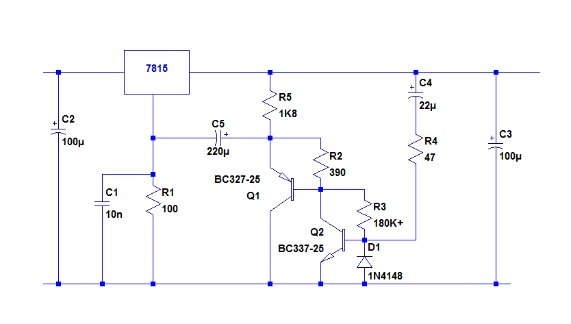
So, I am seeing that we evidently need the additional drive of the Darlington-type circuit for the 7815. Is this because of the low-Ω load (100Ω)?Tested OK....A compensation cap is required, as for other versions; a few nF is sufficient. 10nF is safe.
Now we need another smallish-type board layout (like Hicoco's LM317/337 Add-On) for the 78/7915 retrofits.
Hicoco? Sadface?
The Hicoco LM317/337 Add-on boards have been ordered and are in production.
Last edited:
They are certainly somewhere in the thread, but it will be simpler to repost them.Btw, Elvee, sorry but I couldn't find asc files of yours. Can you share them please?
The RH117 is a native LTspice model.
Other models can be found on the WWW, including the 337, but they are somewhat flaky
YesSo, I am seeing that we evidently need the additional drive of the Darlington-type circuit for the 7815. Is this because of the low-Ω load (100Ω)?
Retrofitting is generally going to be much more complicated than for the 317: the mounting tab is often bolted directly to a grounded heatsink, and the GND pin also goes directly to a GND pad, and often a copper pour.Now we need another smallish-type board layout (like Hicoco's LM317/337 Add-On) for the 78/7915 retrofits.
This means that you would need to lift the center leg and isolate the heatsink.
Certainly possible, but somewhat messy, unlike the 317 which is ideally suited for retrofitting
Attachments
Thank you.They are certainly somewhere in the thread, but it will be simpler to repost them.
The RH117 is a native LTspice model.
Other models can be found on the WWW, including the 337, but they are somewhat flaky
I thought it was for performance benefits like die-noiser. Has 7815 circuit above comparable performance for which one? De-noiser or die-noiser?YesSo, I am seeing that we evidently need the additional drive of the Darlington-type circuit for the 7815. Is this because of the low-Ω load (100Ω)?
Sort of: because the 100 ohm heavily loads the correction amplifier and reduces its gainI thought it was for performance benefits like die-noiser.
Probably somewhere in-between: it cannot achieve the gain of a lightly loaded Die-noiser, but the additional transistor gives it an advantage over the regular denoiserHas 7815 circuit above comparable performance for which one? De-noiser or die-noiser?
Denoiser version 2.0
Hi Guys,
I was a bit bored earlier today so I thought I would take the time to sort out some annoyances I had with my dual rail denoiser board.
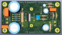
Here is my version 2.0.
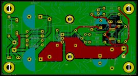
1) R1 and R2 have been moved slightly and increased in footprint size to accommodate up to a 3W metal oxide resistor.
2) A second set of output terminals were added to more easily accommodate powering multiple devices.
3) Extra grounds terminals were added for whatever wacky uses we might dream up.
4) Extra holes have been added so that standard 5.08mm pitch screw terminals can be used in place of Fastons (Thanks to Prasi for this trick)
5) The ground plane was reworked to maximise the use of copper and minimise ground impedance.
6) The basic layout is unchanged but I have reworked the top side traces to make better use of copper pours.
The penalty for the extra outputs was an increased in length by 8mm.
New dimensions are 84mm x 92mm.


Gerber files attached.
This is currently untested by myself.
Hi Guys,
I was a bit bored earlier today so I thought I would take the time to sort out some annoyances I had with my dual rail denoiser board.
Here is my version 2.0.
1) R1 and R2 have been moved slightly and increased in footprint size to accommodate up to a 3W metal oxide resistor.
2) A second set of output terminals were added to more easily accommodate powering multiple devices.
3) Extra grounds terminals were added for whatever wacky uses we might dream up.
4) Extra holes have been added so that standard 5.08mm pitch screw terminals can be used in place of Fastons (Thanks to Prasi for this trick)
5) The ground plane was reworked to maximise the use of copper and minimise ground impedance.
6) The basic layout is unchanged but I have reworked the top side traces to make better use of copper pours.
The penalty for the extra outputs was an increased in length by 8mm.
New dimensions are 84mm x 92mm.
Gerber files attached.
This is currently untested by myself.
Attachments
Hi Guys,
I was a bit bored earlier today so I thought I would take the time to sort out some annoyances I had with my dual rail denoiser board.
Here is my version 2.0.
1) R1 and R2 have been moved slightly and increased in footprint size to accommodate up to a 3W metal oxide resistor.
2) A second set of output terminals were added to more easily accommodate powering multiple devices.
3) Extra grounds terminals were added for whatever wacky uses we might dream up.
4) Extra holes have been added so that standard 5.08mm pitch screw terminals can be used in place of Fastons (Thanks to Prasi for this trick)
5) The ground plane was reworked to maximise the use of copper and minimise ground impedance.
6) The basic layout is unchanged but I have reworked the top side traces to make better use of copper pours.
The penalty for the extra outputs was an increased in length by 8mm.
New dimensions are 84mm x 92mm.
View attachment 849154
View attachment 849156
View attachment 849157
Gerber files attached.
This is currently untested by myself.
Great work. Thanks!
Do you have time for a single-rail version? That'd be amazing if possible.
I can provide the single rail version (LM317) with Sziklai transistors pair, in this thread referenced as dienoiser. PCB uses both copper sides, for low impedance, and has proper Kelvin connection. There are positions for snubber parts as is hard to expect maximum performance without it. ATM, it is untested as well. I have ordered PCBs at last Friday from JLCPCB, but won’t assemble any immediately. Only after several weeks I could confirm if everything is in order with the design. If there is an interest or urgent need, let me know an I will attach gerbers if you are willing to try. PCB dimensions are 50 x 90 mm.
Attachments
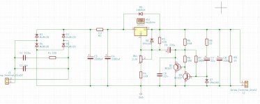
There are positions for snubber parts as is hard to expect maximum performance without it.
And which snubber parts would that be?
Snubber consists of C1,C2 and R1 and those parts are optional. Value of R1 depends on the used transformer. With some luck, exact value for your intended transformer could be found here:
Quasimodo results (ONLY)
More on this topic:
Simple, no-math transformer snubber using Quasimodo test-jig
Quasimodo results (ONLY)
Simple, no-math transformer snubber using Quasimodo test-jig
Yes, I was going to mention that if you want accuracy for the rectifiers and transformer's snubbers you would need a Quasimodo setup, which also involves an oscilloscope, which is quite an expensive piece of equipment. And also know how to use it.
So it's not so simple.
I don't see how your pcb can influence output impedance. Do you have any proof of that? Not even Jung's regulator mentions the PCB layout as affecting impedance. They do mention the Kelvin wiring, but I never saw measurements on that either, comparing using Kelvin or not.
So it's not so simple.
I don't see how your pcb can influence output impedance. Do you have any proof of that? Not even Jung's regulator mentions the PCB layout as affecting impedance. They do mention the Kelvin wiring, but I never saw measurements on that either, comparing using Kelvin or not.
I can provide the single rail version (LM317) with Sziklai transistors pair, in this thread referenced as dienoiser. PCB uses both copper sides, for low impedance, and has proper Kelvin connection. There are positions for snubber parts as is hard to expect maximum performance without it. ATM, it is untested as well. I have ordered PCBs at last Friday from JLCPCB, but won’t assemble any immediately. Only after several weeks I could confirm if everything is in order with the design. If there is an interest or urgent need, let me know an I will attach gerbers if you are willing to try. PCB dimensions are 50 x 90 mm.
That's great thanks!
Very grateful of the CRC snubber on the secondaries. Yes, may need component optimisation, but they can be jumpered so preference is to keep them on.
- Home
- Amplifiers
- Power Supplies
- D-Noizator: a magic active noise canceller to retrofit & upgrade any 317-based VReg