I decided to run a separate topic on S200 so not mixup with other Stasis models and no outdoor activities…
I am a big fan of Nelson amps, always had great time with my 150.5, Fet 10e, S150 mk I, s300 mk II, but I always wanted to listen SA and S optical bias, finally catch S200 optical bias S/N: 04504 (what is the year of manufacturing btw?).
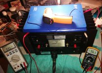
The amp came in so-so condition, so it was fixed, tested, measured (dc offset: right ch 13mV / left ch 107mV), disassembled, cleaned (no bad soldering points found), measured, trim pot replaced, pictured, assembled, adjusted based on the recommendations from DIYAUDIO, thanks to Mr. Pass, Zen Mod, and other beautiful and kind people from this forum.
Here I share some pics and hints I used...
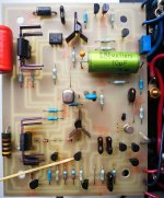
I was surprised to see 2K trim pots on s200 driver boards, and I did not have them at home, so replaced them with 5K Spectrol multiturn, works fine!
Unfortunately, I did not have 0.15 uF film (only 0.1uF) to replace 0.15 uF 35V tantalum (I guess they are optocupler shunt caps) so I left them on until I will be able to shop them.
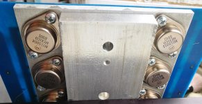
Caps are original grey 15000 uF 75V MEPCO.
I also found that all 1Ohm 2W WW resistors have a bad tolerance from 0.88 up to 1.07 Ohm.
I was surprised to found that 3 Ohm 2W emitter resistors are Carbon Composition… Do I need to replace them with nice Dali WW?
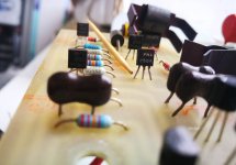
All output transistors are original 15004 (PNP) and 15003 (NPN), 1988 and 1989 year of manufacturing, the rest are: 2N5566, MPSU10, MPSU60, MPSA42, MPSA92, but also a one I never seen in Stasis before – PN4250A (see the pics), but the soldering points looks like original…
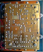
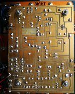
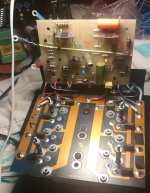
I wash the driver boards with toothbrush and flux cleaning, so they looks nice now.
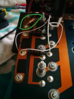
To avoid occasional shorts (heh I had a bad experience before) I solder thin temporary wires across the middle emitter resistor on the positive rail, so it was very convenient to measure the voltage drop and to fine tune, thanks to the multiturn trim tops. Use a pare file as a top cover.
Finally I ended up with 51.1 degree on both sides, with voltage drop of 95,75mV vs 95.5mV per channel after 2H, and it works quite stable, I would say it perfectly tuned. Maybe a bit hot…
DC offset now lowered down to 97mV. Still need advice were to dig to fix.
Also I need an advice on MDA3502 bridge rectifier, which I want to replace with 16A 600V DIY based on HFA08S (which sound signature I like), but I am not sure if this one will have enough current on startup, would appreciate your opinions.
I just want to say, I am in love with this baby, it is far ahead of s150, as I can remember..., so far very positive about optical bias sound signature!
I am a big fan of Nelson amps, always had great time with my 150.5, Fet 10e, S150 mk I, s300 mk II, but I always wanted to listen SA and S optical bias, finally catch S200 optical bias S/N: 04504 (what is the year of manufacturing btw?).
The amp came in so-so condition, so it was fixed, tested, measured (dc offset: right ch 13mV / left ch 107mV), disassembled, cleaned (no bad soldering points found), measured, trim pot replaced, pictured, assembled, adjusted based on the recommendations from DIYAUDIO, thanks to Mr. Pass, Zen Mod, and other beautiful and kind people from this forum.
Here I share some pics and hints I used...
I was surprised to see 2K trim pots on s200 driver boards, and I did not have them at home, so replaced them with 5K Spectrol multiturn, works fine!
Unfortunately, I did not have 0.15 uF film (only 0.1uF) to replace 0.15 uF 35V tantalum (I guess they are optocupler shunt caps) so I left them on until I will be able to shop them.
Caps are original grey 15000 uF 75V MEPCO.
I also found that all 1Ohm 2W WW resistors have a bad tolerance from 0.88 up to 1.07 Ohm.
I was surprised to found that 3 Ohm 2W emitter resistors are Carbon Composition… Do I need to replace them with nice Dali WW?
All output transistors are original 15004 (PNP) and 15003 (NPN), 1988 and 1989 year of manufacturing, the rest are: 2N5566, MPSU10, MPSU60, MPSA42, MPSA92, but also a one I never seen in Stasis before – PN4250A (see the pics), but the soldering points looks like original…
I wash the driver boards with toothbrush and flux cleaning, so they looks nice now.
To avoid occasional shorts (heh I had a bad experience before) I solder thin temporary wires across the middle emitter resistor on the positive rail, so it was very convenient to measure the voltage drop and to fine tune, thanks to the multiturn trim tops. Use a pare file as a top cover.
Finally I ended up with 51.1 degree on both sides, with voltage drop of 95,75mV vs 95.5mV per channel after 2H, and it works quite stable, I would say it perfectly tuned. Maybe a bit hot…
DC offset now lowered down to 97mV. Still need advice were to dig to fix.
Also I need an advice on MDA3502 bridge rectifier, which I want to replace with 16A 600V DIY based on HFA08S (which sound signature I like), but I am not sure if this one will have enough current on startup, would appreciate your opinions.
I just want to say, I am in love with this baby, it is far ahead of s150, as I can remember..., so far very positive about optical bias sound signature!
Last edited:
Ok, just moved them to attachment...
Attachments
-
 left ch.jpg198.9 KB · Views: 415
 -
 threshold_s200-opto_89-90.jpg118.1 KB · Views: 286
 -
 adj_final.jpg112.6 KB · Views: 247
 -
 adj_start1.jpg162.8 KB · Views: 248
 -
 unexpecter transistor1.jpg158.8 KB · Views: 374
 -
 unexpecter transistor.jpg82.8 KB · Views: 361
 -
 output.jpg105.1 KB · Views: 344
 -
 right ch.jpg223.7 KB · Views: 340
C5 isn't critical in value
for output offset - either leave it as is, or try to fine tune R4
which means - read it's value , then replace with fixed resistor and variable resistor (trimpot) in series, so you can alter it +/-20% of original value
for output offset - either leave it as is, or try to fine tune R4
which means - read it's value , then replace with fixed resistor and variable resistor (trimpot) in series, so you can alter it +/-20% of original value
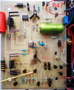
Another idea is to drill the 3rd hole and put trimpot 0.5k instead of R4, or will drift?C5 isn't critical in value
for output offset - either leave it as is, or try to fine tune R4
value
PN - it certainly look originally soldered in, so don't bother
if resistor is 300R, replace it with 270R fixed in series wit 50R multiturn
pre-set to 300R prior to powering on, then fiddle
if resistor is 300R, replace it with 270R fixed in series wit 50R multiturn
pre-set to 300R prior to powering on, then fiddle
Another idea is to drill the 3rd hole and put trimpot 0.5k instead of R4, or will drift?
better as I described
lesser chance to go out of safe area
Sure, agree! Thank you! will check if I have small value trimpot at home.better as I described
lesser chance to go out of safe area
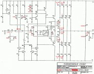
One more question.... there are two carbon composition resistors 3 Ohm 2W each. What are their purpose and why are they CC but not film or WW?
Do the resistors that look like Carbon Comp have wider first color band? If so the wide band signifies wire wound.
Craig
Craig
Last edited:
Do the resistors that look like Carbon Comp have wider first color band? If so the wide band signifies wire wound.
Craig
As per the known scheme with components list of the first gen, these two are CC
Attachments
All emitter resistors were replaced with 2.5W Dale NS-2C non-inductive resistors.
The result is audible, more space, more details, more natural.
Maybe Panasonic film resistors will give better result, but I am pleased with Dale.
The open question if I need to replace the above mentioned CC pair? It should be a reason to place CC there...
The result is audible, more space, more details, more natural.
Maybe Panasonic film resistors will give better result, but I am pleased with Dale.
The open question if I need to replace the above mentioned CC pair? It should be a reason to place CC there...
Attachments
I can't think of any possible reason why there should be only CC
Zen Mod,
Finally got the parts and time...
After R6 300Ohm replaced with 330Ohm both channels shows just perfectly equal figures ~11mV dc offset.
After R27, R26 3W resistor removed, it measured as 3.3 Ohm which is different from schematics.
I do not know if this is a bug of feature, and how the 3 Ohm replacement can influence the amp, please advice?
3R3 is sorta standard and difference from 3R to 3R3 is irrelevant
besides, 0R3 difference - you need something else than DMM to measure that precisely (probes together - what's reading?)
put them back, or put new ones (3R3) and enjoy
besides, 0R3 difference - you need something else than DMM to measure that precisely (probes together - what's reading?)
put them back, or put new ones (3R3) and enjoy
Hi there, sorry to revise an old thread but I recently purchased a S200 that's having issues. One channel has very low sound output and a tremendously high dc offset of 3 volts. Do you have any advice on how to fix it? Also, do you have a parts list for what you used when rebuilding the amp? I'd love to try to tackle the problem myself.
Interesting that I just found this zombie(?) thread days after it was revived.
Okay, maybe not, since it is now a "recent" post.
I'm following, as I have a well-functioning s200 powering my main rig (that I wish was much larger. like s600 large).
Anyhow, anything above 100mV DC offset is big; 150 mV is HUGE. Make sure that you are shorting the inputs for an accurate offset measurement.
You appear to be at 20x HUGE, which requires more capital letters.
Again, make sure nothing is connected, other than shorted plus and minus input terminals.
Among other resources, check out Hoppe's Brain (Adcom-centric, but whatever):
Hoppe's Brain | DIY circuit board kits for Adcom and DIY Amplifiers
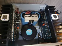
Marriy Christmas and Happy New Year to all beautiful people in here!)
Paired MIJIA smarthome with Threshold amp. =)
Just open the lid, turn the pot, close the lid and control the temp via app. Repean until you done it.
Easy and precise))
Have fun!
Paired MIJIA smarthome with Threshold amp. =)
Just open the lid, turn the pot, close the lid and control the temp via app. Repean until you done it.
Easy and precise))
Have fun!
Attachments

- Home
- Amplifiers
- Pass Labs
- Threshold S200 of offset, bias adjustment and other things at this COVID-19 times