Hello mates
I'm repairing a big korean amplifier a 6k.
I've done a full rebuild on the PS section. New drivers, new irf3205 which are from reputable source - farnell, gate resistors, pull down resistors and etc.
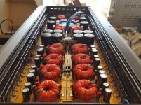
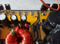
The problem is that one of the bank, keeps driving the PS mosfets into short. Only this bank, as seen on the photo.
If there are no PS mosfets fitted in this bank, gate drive is good and strong, no problems.
As soon as I fit new FETS - excessive current and the 4 fets which are the one driving the problematic transformer are shorting out.
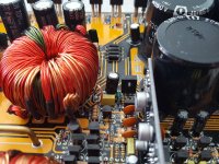
I've pulled out the transformer. PS section now works but the rail voltage are not correct due to the missing bank of ps section.
There are no solder bridges. I've pulled out the transformer and can't really see if there is a short without unwinding it (i don't think i'm capable of rewinding it).
Is there a way to check if the transformer is shorting out or not ? There is no short between the winds, but i suspect it is shorting into the core ? Any ideas ?
I'm repairing a big korean amplifier a 6k.
I've done a full rebuild on the PS section. New drivers, new irf3205 which are from reputable source - farnell, gate resistors, pull down resistors and etc.
The problem is that one of the bank, keeps driving the PS mosfets into short. Only this bank, as seen on the photo.
If there are no PS mosfets fitted in this bank, gate drive is good and strong, no problems.
As soon as I fit new FETS - excessive current and the 4 fets which are the one driving the problematic transformer are shorting out.
I've pulled out the transformer. PS section now works but the rail voltage are not correct due to the missing bank of ps section.
There are no solder bridges. I've pulled out the transformer and can't really see if there is a short without unwinding it (i don't think i'm capable of rewinding it).
Is there a way to check if the transformer is shorting out or not ? There is no short between the winds, but i suspect it is shorting into the core ? Any ideas ?
Attachments
It's generally best not to pull an inductor or transformer that you suspect has a shorted winding. Pulling it shifts the windings and can make the intermittent short temporarily seem to be gone.
The transformer that's shorted isn't necessarily the one with the failing FETs.
I'd power it up through a limiter and try twisting/pushing/pulling on all of the transformers.
The transformer that's shorted isn't necessarily the one with the failing FETs.
I'd power it up through a limiter and try twisting/pushing/pulling on all of the transformers.
I'd power it up through a limiter and try twisting/pushing/pulling on all of the transformers. - done that, does not make any change.
The bank of 4 fets are only tied to this transformer and two drivers. The transformer itself is in parallel with the other 7 ones.
If fets are new and fine, drivers are new and fine, resistors and diodes (i've checked even the rectifiers) there is pretty much nothing else to make short except the transformer.
Forget to mention that amp was mounted in a HEAVY SPL car with a lot of vibration (around 160db+) .
Have the FETs failed since the transformer was removed/reinstalled?
You could try heating the transformer with a heatgun (carefully if it's the type that's used to melt paint).
You could try heating the transformer with a heatgun (carefully if it's the type that's used to melt paint).
You can test a transformer by removing it and putting it in series with resistor and capacitor.
Apply a sine wave to the series RLC circuit and see what frequency the sine wave is least across LC. Compare that to the other transformers.
Also apply a sine wave through a resistor to the primary and see if teh secondary voltage is scaled the same as a good transformer.
minimum f=1/(2 pi sqroot(LC))
Have the FETs failed since the transformer was removed/reinstalled?
Taking out the problematic transformer leaves the bank of the 4 mosfets with no voltage applied to the drain. So there is only gate and source. Drain does not get its 12v due to the missing transformer.
So the Mosfets don't actually do anything when the transformer is out, no drain voltage.
I have not reinstalled the transformer due to this being lengthy process and not being sure if the transformer is shorted or not.
Last edited:
Do these transformers have 4 terminals on the secondary?
Are you sure that the secondaries are in parallel and not in series?
Are you sure that the secondaries are in parallel and not in series?
Do these transformers have 4 terminals on the secondary?
Are you sure that the secondaries are in parallel and not in series?
Yes they do, they are 4 terminals on the secondary.
They are in series 2*2 and then all in parallel. I have a schematic from a similar but not the exact same model, as this was the best i could find.
I've fitted the transformer (its under T8) back to its place. Took out the irf3205 from this bank in order not to blow them again.
Mosfets out:
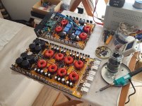
1st picture amp
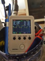
2nd - is the gate drive
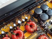
3rd - is the drain pads of the mosfet
Now what got me baffled is picture 4. C51 was a 35v 100uf cap. If i leave the amp for a little bit longer it keeps blowing up. Voltage around 60v and this was only a 35v cap.
I do not understand why its ground is directly connected to the negative rail and its positive to D20 and D23 cathodes. And why the heck D21 and D22 anodes are in short with the negative rail ?
These should be the auxiliary voltage for the voltage regulators 7812/7812A.
In the schematics i found, the auxiliary voltages does not share anything with the rail voltages.
Perry I can send You the schematics but they are not 1:1 with the board in front of me.
I'm not sure it's the transformer now, but there is a short somewhere...
Attachments

Confirm that the windings that drive the 4 diodes D20-23 are completely isolated from all other windings on the transformer.
Those windings are referenced to the negative rail via the diodes D20 and D23. The two regulators are for the 21844s.
Those windings are referenced to the negative rail via the diodes D20 and D23. The two regulators are for the 21844s.
Confirm that the windings that drive the 4 diodes D20-23 are completely isolated from all other windings on the transformer.
Those windings are referenced to the negative rail via the diodes D20 and D23. The two regulators are for the 21844s.
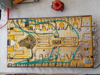
They are isolated, but are in short with one another, the ones near the 10R/1W resistor.
Picture attached.
I've also drawn the connection with different colors between D20-D23 and the cap. Should D20-D23 be they all bridged at the left side ?
Attachments

Did you have 24v of drive on the primary windings?
How did you connect the scope to the aux windings?
How did you connect the scope to the aux windings?
Rather than a bad transformer I´d suspect what´s killing your drive Mosfets is the load at the other end of the transformer: shorted rectifiers - supply caps - amplifier.
I´d replace drive Mosfets once more, disconnect secondary from all loads and since switching transformers and drivers probably won´t like to work fully unloaded, I´s load each secondary with a 100W bulb or similar.
If bulbs light system is working up to that point.
Not suggesting bulb voltage yet because I don´t know expected secondary voltage but in principle I´d use quite higher than expected, we don´t want bulbs to blow and help nothing about your problem.
Say, if you have 35 to 60V secondaries I´d use 120V bulbs.
We are not trying to closely match load by any means, just functionally testing circuit blocks.
If test works , I´d add elements one by one.
Say add diodes and light bulbs with rectified output, then if good add capacitors and so on.
Go step by step.
I’m new to this, but after having some issues with an inductor i figured out that instead of soldering it back to the board while still troubleshooting, i soldered some coper wires to the board and then the transformer to them wires. It really minimized the heat exposure to the board and aggravation from having to remove the transformer several times.
PS section is being tested isolated from the amplifier section. I got lucky this one is built by separated module sections.
Supply caps have beet tested and even changed, rail caps also tested, rectifiers tested too. And the last two would indicate problem due to the fact they are being shared by all of the power supply "banks".
"Did you have 24v of drive on the primary windings?" - i will take a picture exactly what's going on the primary windings while mosfets are fitted in. Of course I will limit the current to 2-3Amps in order not to blow another batch of 3205s.
"How did you connect the scope to the aux windings?" - should i use primary or the secondary ground as a reference ? There is only 1k resistor between the primary and secondary gnd.
I still suspect the transformer is shorted to it's core due to rubbing caused by high vibration.
I will take additional measurements when i get back home.
Attachments
Last edited:
After the aux winding is disconnected from the board, check it for shorts to the main windings.
With the aux winding completely disconnected, you'll connect the scope ground and the tip of the probe to the two ends of the wire. Do this only after you're sure that there is no connection between the aux winding and the rest of the windings.
With the aux winding completely disconnected, you'll connect the scope ground and the tip of the probe to the two ends of the wire. Do this only after you're sure that there is no connection between the aux winding and the rest of the windings.
Rather than a bad transformer I´d suspect what´s killing your drive Mosfets is the load at the other end of the transformer: shorted rectifiers - supply caps - amplifier.
I´d replace drive Mosfets once more, disconnect secondary from all loads and since switching transformers and drivers probably won´t like to work fully unloaded, I´s load each secondary with a 100W bulb or similar.
I suspect the transform is the issue mainly to the fact that this amp was in an over 160db+ 15hz-50hz show demo car. This is the second amp coming from this car with the kind-a same issue.
First one was a 4 channel class AB with direct short between the windings in one of the power transformers.
So far i've never had issues to take out the rectifiers and test the power section ?! Why would "switching transformers and drivers probably won´t like to work fully unloaded" ?! 😕
Sorry to be late tpo the party, but something I don't understand.
If I understood correctly, you said that the PS is OK with no output MOSFETs, but is shorted with the output MOSFETs.
Why then do you think the xformer has a short? If it had, how come the PS is good without the output MOSFETs?
Jan
If I understood correctly, you said that the PS is OK with no output MOSFETs, but is shorted with the output MOSFETs.
Why then do you think the xformer has a short? If it had, how come the PS is good without the output MOSFETs?
Jan
- Home
- General Interest
- Car Audio
- How to find a short in transformer (korean 6k amp)