Good! Thanks for help Piotr. Weeked spent over LTspice and tube amp designing books, sure was a lot of fun! 😀
rplate,
In your first post you ask for help and some fine experienced people have come forth to lend a hand and you question what they have to say. Most have years of experience and generally can do the calculations in their head. Some have suggested nicely to adopt a different tube lineup and you want to stick with what you have.
Been there and done that and sure it makes you feel good to have something that you put together from a shoe box of tubes and components. Rational thought needs to rear its head in here pretty quick to let you know that some designs yeald very low power and increased distortion over other designs. I would suggest that unless your hell bent on using the tubes you have a quantity of you simply listen to those with experience. The results will be far better and maybe you can use your tube stash on another project when you obtain more skill and experience.
Since I threw caution to the wind before and put together a very nice sounding 1.5 watt per channel amp the results of the amplifier left me wanting more every time I used it. Don't get me wrong what I pieced together sounded great but to be blunt left me wanting more and more level. It is my belief that while you might be satisfied with something in the 1 watt range that it won't take long before you start to question your reasoning for wasting the parts on something so ineffective.
Last edited:
rplate,In your first post you ask for help and some fine experienced people have come forth to lend a hand and you question what they have to say.
I meant no disrespect by any means, so please excuse me, if it felt that way from my previous posts.
I would suggest that unless your hell bent on using the tubes you have a quantity of you simply listen to those with experience.
I hear you.
Let's put it this way at this point in my shoe box I have GU-50, 6P1P, and 6P3S output tubes, are they worth trying? Maybe I can use 6N6P as a driver?
Or should I look for different tubes to obtain satisfactory results?
No, at best, you’re just repeating other people’s mistakes. Especially if you’re not actually experimenting.*but by doing it yourself you are actually learning right?
Look at all those schematics, particularly those from well financed engineers (e.g. WE), the early iconoclastics (hello jc morisson and Kondo-san) and understand what the heck is going on.
Because experimenting means having a theory based on the current literature and testing it with appropriate measurements.
At least download RDH and work out whether you’re in the same state as “well engineered “
Last edited:
Actually 1-watters aren't that bad 🙂rplate,
It is my belief that while you might be satisfied with something in the 1 watt range that it won't take long before you start to question your reasoning for wasting the parts on something so ineffective.
While this kind of power output is definitely not enough for serious listening of quality records, those little amps work great for less demanding applications - as the PC desktop or bedroom amp, for example. And they are probably the better choice for a first build.
6P1P are nice little tubes of the 6V6/6P6S family (basically 6AQ5 with the noval base). Search for El Cheapo amp on this forum, for example.Let's put it this way at this point in my shoe box I have GU-50, 6P1P, and 6P3S output tubes, are they worth trying?
6P3S are of 6L6 family - not great, not terrible (that's my personal opinion, a lot of folks love them).
GU-50 are actually very good (though ugly), but they are not for beginners.
You can, but that would be very far from optimal.Maybe I can use 6N6P as a driver?
No, at best, you’re just repeating other people’s mistakes. Especially if you’re not actually experimenting.*
Look at all those schematics, particularly those from well financed engineers (e.g. WE), the early iconoclastics (hello jc morisson and Kondo-san) and understand what the heck is going on.
Because experimenting means having a theory based on the current literature and testing it with appropriate measurements.
At least download RDH and work out whether you’re in the same state as “well engineered “
You have a very strong point here, Sir.
I am done with "I will design for myself" gibberish. I would like to learn though, but probablly this means phd in EE 😀
6P1P are nice little tubes of the 6V6/6P6S family (basically 6AQ5 with the noval base). Search for El Cheapo amp on this forum, for example.
As I understood El Cheapo could work with 6P1P and 6NxP (x = 1,2,3)? Are there any good examples of 6P1P in SE configuration? Or it lacks power?
Last edited:
You can probably make it work with those tubes, but all three of them are sub-optimal.As I understood El Cheapo could work with 6P1P and 6NxP (x = 1,2,3)?
12AT7/ECC81 is quite unique - it has high amplification factor (which you need for this design) while plate resistance is still reasonably low (which is also a good thing).
If I absolutely had to stick with 6Ns, I would probably choose 6N2P (with appropriate schematics modifications, of course)
Look for 6V6 or 6AQ5 SE amps.Are there any good examples of 6P1P in SE configuration?
1.5-2W in triode mode, about twice as much in tetrode.Or it lacks power?
One of the joys of zero-feedback amplifiers is that you don't need to do (or understand) complex number arithmatic nor understand Nyquist nor do Bode plots.I am done with "I will design for myself" gibberish. I would like to learn though, but probablly this means phd in EE 😀
You do need to be able to calculate 3db points based and understand what the Miller effect is. And that transformers and capacitors are far more complex than the official ideal model.
Plus basic valve safety. e.g. Rob Robinette's safety article
Being able to "read" a set of valve curves is also a benefit although these days whether a valve actually behaves anything like the prototypical curves is a bit of a crap shoot.😡
Now the bad news: good iron does require both materials and skill to create. If you can afford Lundahl you're home and hosed (they're "the knee" in the quality curve). If not, you need to work a bit harder.
The other bad news: building near-ideal capacitors is also challenging, leading many to pick iron over caps (see this Lynn Olson article for some history) and some to flee to PP to avoid that problem
The other other bad news: really, really good valves are like iron. Hence NOS 45s go for serious money.
The other good news: you can get a long way on not a lot of money. Especially if you can compromise on absolute power (forget anything other than triodes or triode mode) and the bass 3db point.
Case in point: I made a little 6S4A SE amp a while back (ab)using some 100V PA iron. Barely 750mW and nothing much below 50Hz. But sweet, sweet music. And by that I mean (almost) one good, clean watt, not 2nd harmonic-laden mush. (One day I'll do a PP version using the same iron and get ten decent watts....)
I could write (and probably have) written thousands of words as to why this is so but I'd rather pass on one more tip: the power supply is as important as the amplifying stages.
Getting a low noise, mains-line-rubbish rejecting PS circuit is as important as ensuring your output device is operating in the most linear range you can find.
If there is one thing you should learn it is that current travels in loops. This has massive implications on physical circuit design, and particularly layout. The same schematic can sound completely different when lain out differently, mostly around hum, noise and stability.
Last edited:
Given that current travels in loops, try and find two operating points for your valves such that the variation in the current usage of the second stage is exactly equal and opposite to the usage in the first stage, powered from a common source.
This means the current now simply circulates within the circuit, no matter what the volume is set to, and all that your power supply ever does is provide a steady constant bias current.
Sound quality should thus be less dependent on how good the power supply and earthing arrangements are, because no signal is sharing that loop.
kind regards
Marek
MarekH,
Usually the driver stage has less quiescent current than the output stage quiescent current.
And usually the driver stage signal current is less than the output stage signal current.
You are not going to get any power drain cancellation that way.
Please give us an example of a 2 stage amplifier where the currents are opposite in phase and equal signal current values (and I do not mean the obvious topologies of a Push Pull Output stage, nor of an LTP phase invertor stage).
I think we should pay attention to thoglette's words about having a good power supply.
As to loops, here are 2 examples of B+ loops (as in Hum loops).
1. Full Wave rectified B+. Connect the B+ secondary center tap to the negative of the first filter cap, connect a second wire from the negative of the first filter cap to the negative of the second filter cap.
From the negative of the second filter cap, connect another wire to the central amplifier ground point. These B+ first local loop capacitive currents are prevented from going into the central ground point . . . resulting in less hum.
Reducing the charge currents to local loops, reduces the following problems.
A. Wires are also resistors (A capacitive transient current of 1/2 Amp in a 10 milliohm wire creates a "hum signal" of 5mV. Apply that voltage into the input stage's self bias resistor and bypass cap (injecting 5mV into the cathode), and you get lots more than 5mV hum at the amplifier speaker output terminals.
B. There is the inductance of the same wire. Capacitor charge currents are very transient in nature, and there are lots of harmonics there (and those hum harmonics are at frequencies where the ear is more sensitive). A 10 Inch ground wire has perhaps 100nH of inductance. At 2kHz, that 100nH is 1.2 milli-Ohm of inductive reactance. That same 1/2 Amp capacitor charge current might develop 1.2mV into the cathode circuit of the input tube. Lots more coming out of the speaker terminals.
C. The 1/2 Amp transient traveling through a 10 Inch wire is going to create a large magnetic field, which may be picked up by other wires in the amplifier.
2. Full wave rectified B+. Connect the B+ secondary center tap to the central amplifier ground point. Connect the negative of the first filter cap to the amplifier central ground point. Connect the negative of the second filter cap to the central amplifier ground point.
These transient capacitive currents are all going to the central ground point . . . resulting in more hum.
This kind of careless connections in 2. above, causes A. and B. and C. above to take over the control and out of the amplifier designers hands.
Last edited:
6A3sUMMER,
The first stage and splitter on Norman Koren's TENA amplifier is an example where you have both gain and run at constant current. The variation in current usage by his first gain stage is equal and opposite the variation in his splitter so the whole lot runs at constant current.
We were asked for opinions and as I see it, the fundamental flaw in single ended designs is that they modulate the power supply. The fundamental flaw in push-pull designs is that they start equally unbalanced.
What I'd was suggesting was to design that away.
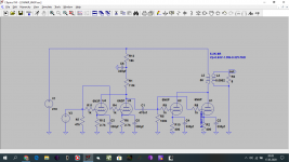
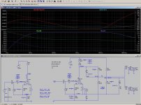
The following attached sacrifices most of its gain to set up a directly coupled push-pull next stage (although that's not exploited here - this is just an example building block with the values tweaked to prove a point). It takes a 0.5v unbalanced input and outputs balanced 1.3v outputs sat on a 223v dc rail to hang the next stage on.
The stated objective was to have a bit of fun designing something and having access to LTSpice means being able to test it and see how the dynamics move around long before having to worry about committing to hardware.
kind regards
Marek
The first stage and splitter on Norman Koren's TENA amplifier is an example where you have both gain and run at constant current. The variation in current usage by his first gain stage is equal and opposite the variation in his splitter so the whole lot runs at constant current.
We were asked for opinions and as I see it, the fundamental flaw in single ended designs is that they modulate the power supply. The fundamental flaw in push-pull designs is that they start equally unbalanced.
What I'd was suggesting was to design that away.
The following attached sacrifices most of its gain to set up a directly coupled push-pull next stage (although that's not exploited here - this is just an example building block with the values tweaked to prove a point). It takes a 0.5v unbalanced input and outputs balanced 1.3v outputs sat on a 223v dc rail to hang the next stage on.
The stated objective was to have a bit of fun designing something and having access to LTSpice means being able to test it and see how the dynamics move around long before having to worry about committing to hardware.
kind regards
Marek
Attachments
- Home
- Amplifiers
- Tubes / Valves
- SE amplifier design process