I'm not sure when the microphone will arrive, given the current conditions, but I'll try to keep you updated.
The components and the microphone arrived today.
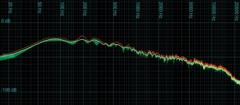
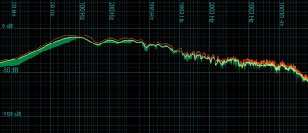
I assembled the crossover and connected it to the speaker and ran a quick pink noise FR measurement, and a background noise measurement. The pictures below are the screenshots from the audio analyser tool I used with my microphone from approximately 0.5m from the face of the speaker.
I live in the country side so i can also go out in my garden to do some free field measurements, to see how close the model is to the real thing.
If you have any suggestions for what I should measure, I'd love to hear them. I only have a microphone, amplifier, and a multimeter at hand.
PS the first image is the baseline measurement, the second is with a pink noise generator running.
Attachments
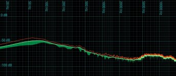
I would prefer to have a little more bite in the higher frequencies, as you can see in the graphs its lacking in that region. In person it also sounds a little dull as you might imagine.
I didn't solder the crossover components, I just twisted the leads together, could this be a reason why the highs are so low?
I didn't solder the crossover components, I just twisted the leads together, could this be a reason why the highs are so low?
Last edited:
The whole midrange and treble looks far too low in level. Everything should be flat from about 200hz and up.
I haven't been following this thread much but IIRC people have been simulating the crossover for you? There's obviously far too much baffle step correction and the large inductor needs unwinding to bring the midrange up.
If you just keep simulating and making new crossovers it will take forever guessing what the right level should be, and will cost a fortune in components.
If you could unwind the large inductor and only have that component inline with the woofer (don't bother with the tweeter) or any other components. Just keep unwinding it, bit by bit, whilst taking measurements (don't cut the wire because you may need to wind it back after the new crossover is simulated). Until the frequency response is flat from 200hz and up to about 1000hz. Once you've done this and measured the inductor, someone can input this value into software and use that as a reference. Obviously in the software it will look like the speaker has a rising response, but will be flat in reality.
Before anyone says it. The value of inductor you come up with if you follow my guide is unlikely to be correct for the finished crossover because once you start adding further components, you get reactance. It's so you know what the frequency response should look like in the software, because at the moment flat in the software isn't flat in reality.
Edit: This is all assuming your measurements are correct obviously.
Edit: This is all assuming your measurements are correct obviously.
Last edited:
@fatmarley
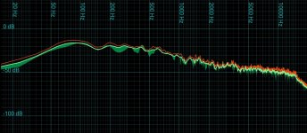
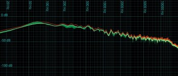
I've removed the 5.6 ohm resistor from the tweeter, this results in an incline at HF. I've also removed the 0.68 ohm resistor from the woofer side. They resulted in the below images. Next I will try unwinding the small inductor as that increased the sound level at a higher frequency range than a decrease in the large inductor's inductance would. This should result in a smoother incline.
I've removed the 5.6 ohm resistor from the tweeter, this results in an incline at HF. I've also removed the 0.68 ohm resistor from the woofer side. They resulted in the below images. Next I will try unwinding the small inductor as that increased the sound level at a higher frequency range than a decrease in the large inductor's inductance would. This should result in a smoother incline.
Attachments
@fatmarley
I've removed the 5.6 ohm resistor from the tweeter, this results in an incline at HF. I've also removed the 0.68 ohm resistor from the woofer side. They resulted in the below images. Next I will try unwinding the small inductor as that increased the sound level at a higher frequency range than a decrease in the large inductor's inductance would. This should result in a smoother incline.
Don't bother messing with the small inductor. It's the 1.8mh you need to unwind
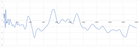
This is the microphone's response btw. This might explain the low level measurements of the HF range a little.
The y-axis is in dB.
Oh, are you saying it's not a calibrated microphone?
How to take quasi-anechoic measurements: Box
How to find relative acoustic centers: Box
REW - Room EQ Wizard Room Acoustics Software
How to find relative acoustic centers: Box
REW - Room EQ Wizard Room Acoustics Software
@fatmarley
I've removed the 5.6 ohm resistor from the tweeter, this results in an incline at HF. I've also removed the 0.68 ohm resistor from the woofer side. They resulted in the below images. Next I will try unwinding the small inductor as that increased the sound level at a higher frequency range than a decrease in the large inductor's inductance would. This should result in a smoother incline.
If you've removed the tweeter resistor, this shows your measurements are very wrong. The tweeter should measure with higher SPL than the midbass.
I have a pair of mission 710 that I am using as reference for the mid to high range. So if there is anything wrong with the measurements the error will be constant.
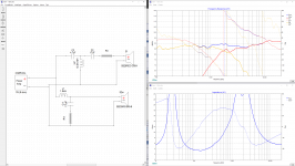
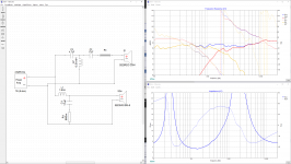
So far I've removed the resistors, and unwound the large capacitor down to 1.3mH, and the small one to 0.3mH. I've attached the simulation, and the measured output, plus the measurement with only the resistors removed for comparison.
So far I've removed the resistors, and unwound the large capacitor down to 1.3mH, and the small one to 0.3mH. I've attached the simulation, and the measured output, plus the measurement with only the resistors removed for comparison.
Attachments


I have a pair of mission 710 that I am using as reference for the mid to high range. So if there is anything wrong with the measurements the error will be constant.
So far I've removed the resistors, and unwound the large capacitor down to 1.3mH, and the small one to 0.3mH. I've attached the simulation, and the measured output, plus the measurement with only the resistors removed for comparison.
I wouldn't unwind the inductors or mess with the crossover any more. You need to get your measurements right first.
Have a good read of post #110
I've found my mistake, and its very stupid. I have been using pink noise to measure the speakers up until now, pink noise has a downward slope with frequency, thats why the measurements are sloping.
Don't mess with the crossover components... yet.
First - you need to have reliable data.
Re-read the articles linked in jReaves post #110. It is vital you get good consistent measurements. These should be done without any crossover in place. When measuring the tweeter - use your multi-meter on the test signal to ensure no more than 0.5v is output from the amplifier. That's a perfectly safe level to get reliable full range measurements unless you are in a very noisy environment. Alternatively, you can increase level but increase the starting sweep frequency in REW. Personally I feel safer with 0.5v input. Try both sine wave and white noise
Now for the microphone - what are you using and have you loaded the calibration file?
Post the raw measurement graphs of each driver here. We need to first confirm your baseline data is good. Otherwise your crossover changes are really a crapshoot in the dark.
Also - don't use such a huge Y axis scale - a range of 40dB to 95dB is good for an overview
Making good quasi-anechoic measurements takes time. It is not difficult per se, but it requires a sorting-out process where you systematically remove all of the sources of error from your test setup. Read the links that jReave posted.
Your goal should be to measure the drivers (not the finished system) installed in your cabinet. If you don't yet have a cabinet, you should mock-up a baffle and put the drivers in it. Once you have captured the FR of both the woofer and the tweeter, including the baffle step and diffraction effects of your unique baffle shape, then you can tweak the crossover in XSim.
Your goal should be to measure the drivers (not the finished system) installed in your cabinet. If you don't yet have a cabinet, you should mock-up a baffle and put the drivers in it. Once you have captured the FR of both the woofer and the tweeter, including the baffle step and diffraction effects of your unique baffle shape, then you can tweak the crossover in XSim.
It shouldn't be necessary to find the acoustic centres if woofer and tweeter are measured from the same distance, as the information will be right there in the measurements.
The idea of converting the response to minimum phase and simulating the physical separation is risking accuracy needlessly in both respects.
IMO it really comes down to whether you're using a single or dual channel system. In a single channel system the system delay is unknown and the best the measurement software can do is place the peak of the IR at t = 0 for both measurements. As a result, the phase differences due to acoustic offsets is lost. So when using a single channel system I use minimum phase and the three measurement approach to determine the acoustic offset between the drivers. I would call that measuring the offset, not simulating it.
With a dual channel system the exact excess phase (i.e. time of flight, etc.) is known so I would agree with you.
Last edited:
I can think of many reasons why a person might take a measurement that way, but it would have to be called unusual.
Say you used a dual channel programme, say REW, but with only one channel. You are able to set the gate by the beginning of the impulse, of course then you have to set the offset manually. However converting what you have there to minimum phase may cause further unnecessary changes, I can't see the benefit.
Say you used a dual channel programme, say REW, but with only one channel. You are able to set the gate by the beginning of the impulse, of course then you have to set the offset manually. However converting what you have there to minimum phase may cause further unnecessary changes, I can't see the benefit.
I'm getting my calibrations done in REW, but I've hit a will with calibrating my sound card. Do you have any recommendations as to how I should do this calibration without destroying an audio cable? I would need to take the audio output and loop it back to the microphone input.
- Home
- Loudspeakers
- Multi-Way
- Designing an 8" 2-way using the SB23NRXS45-4 and SB29RDC-C004