Please review my active Crossover schematic and provide suggestions and improvements.
I do not have experience in designing any electronics, but have experience designing passive speakers. and Crossover the design itself is mostly gathered from online articles. and ESP projects.
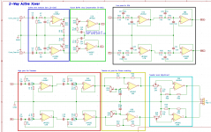
Attached a schematic of VituixCAD to that I will be using to simulate the final output
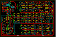
Also mocked up a PCB based on the schematic,
Any help provided is really appreciated.
Cheers
I do not have experience in designing any electronics, but have experience designing passive speakers. and Crossover the design itself is mostly gathered from online articles. and ESP projects.
Attached a schematic of VituixCAD to that I will be using to simulate the final output
Also mocked up a PCB based on the schematic,
Any help provided is really appreciated.
Cheers
Attachments
Last edited:
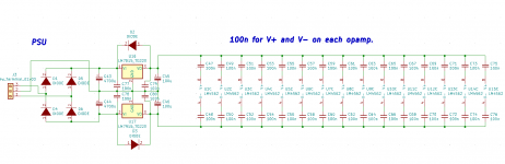
All the power supply 100nF bypass caps seem to have the wrong ends going to the ICs.
Those ends all should go to ground instead. With the present layout however, it would be
much easier instead for just one 100nF capacitor to be between V+ and V- per IC package.
Also I don't see a connection from the main supply ground to the audio ground GNDA.
Those ends all should go to ground instead. With the present layout however, it would be
much easier instead for just one 100nF capacitor to be between V+ and V- per IC package.
Also I don't see a connection from the main supply ground to the audio ground GNDA.
Last edited:
All the power supply 100nF bypass caps seem to have the wrong ends going to the ICs.
Those ends all should go to ground instead. With the present layout however, it would be
much easier instead for just one 100nF capacitor to be between V+ and V- per IC package.
Also I don't see a connection from the main supply ground to the audio ground GNDA.
Thank you!!!.
I will correct the schematic for the caps and ground.
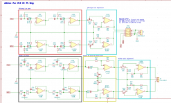
The 100n caps in the all-pass circuits are way too big, should be more in the 10n range for tweeter delay use. And if you actually need the delay, it's likely one first order all-pass stage won't be enough to do the job...either more first order stages or higher order filters are generally necessary.
Mike
Mike
Last edited:
The 100n caps in the all-pass circuits are way too big, should be more in the 10n range for tweeter delay use. And if you actually need the delay, it's likely one first order all-pass stage won't be enough to do the job...either more first order stages or higher order filters are generally necessary.
Mike
Thanks mike, you are correct, the tweeter allpass needs around 10n and subwoofer around 100n.
For most 4,5,6 inch drivers with offset upto 1 inch, was able to make do with single allpass in my vituixcad sim.
a single all pass should cover 180 degrees of phase shift, if more is needed, we can always reverse the driver polarity.
Attached updated schematic.
Cheers.
Attachments
Last edited:
7.5nF may be hard to source, caps are generally most available in E3 and E6 values, not so much E24. However two 15n in series will work, so add extra pads under than assumption.
7.5nF may be hard to source, caps are generally most available in E3 and E6 values, not so much E24. However two 15n in series will work, so add extra pads under than assumption.
values between 1n to 10n are available in E24, above that we generally get E6 or E12 at best. The PCB foot prints are based on Kemet PHE426 series which are good quality caps and reasonably priced. available on mouser..
Infact, my idea was to buy 7.5n and 15n in bulk and keep changing resistor values, as resistors are cheaper and available in a wider range of values, easy to source x,2x values. Please see the spreadsheet attached.
Cheers.
Attachments
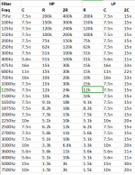
In fact, my idea was to buy 7.5n and 15n in bulk and keep changing resistor values
Good idea. At each output, I would add a 100R series resistor.
Thanks mike, you are correct, the tweeter allpass needs around 10n and subwoofer around 100n.
For most 4,5,6 inch drivers with offset upto 1 inch, was able to make do with single allpass in my vituixcad sim.
a single all pass should cover 180 degrees of phase shift, if more is needed, we can always reverse the driver polarity.
Attached updated schematic.
Cheers.
OK, but phase shift, while similar, is not the same thing as actual time delay. You may be able to get it close with phase manipulation, but it's not really a true substitute for time delay. The system I'm building now would only require about 15 uSec to line up perfectly...but that much difference isn't enough to compell me to use any at all, and I'd be surprized if you actually needed any delay between the woofer and mid at all.
I'm a big fan of minimizing the number of stages in my designs to keep the noise and distortion as low as possible.
Mike
My understanding is that time delay in analog domain is the same as shifting phase. Phase Correction - Myth or Magic Mr Elliot calls them phase shift networks.
I agree , phase shift on woofer is not required when crossed under 200. I am thinking of adding a switch to bypass it, saves parts when not needed.
The use case I had in mind for phase shift on woofer is when crossed higher. Woofer+Dome mid+ tweeter kind of situation.
Cheers
Last edited:
My understanding is that time delay in analog domain is the same as shifting phase.
Phase shift is equivalent to a time delay only when the phase shift is linear with frequency.
An RC low pass filter, for example, has an arctangent function phase curve, not linear.
Phase shift is equivalent to a time delay only when the phase shift is linear with frequency.
An RC low pass filter, for example, has an arctangent function phase curve.
Okay, I thought it was similar to passive crossovers.
What is the formula to calculate X delay at Y frequency for the liner phase shift.
Is there a way to implement second order all pass with a single opamp?
(Trying to keep the part count down)
Cheers
Okay, I thought it was similar to passive crossovers. What is the formula to calculate X delay at Y frequency
for the liner phase shift. Is there a way to implement second order all pass with a single opamp?
The same constraint applies for either active or passive filters.
The time delay is defined as: Td = - d(phase) / d(frequency)
If the phase is linear with frequency, then phase = constant x frequency.
Td = - d(phase) / d (frequency) = - d(constant x frequency) / d (frequency) =
- constant x d(frequency) / d (frequency) = - constant = Td
This is a straight line, sloping downward on the phase vs. frequency graph.
Td (in seconds) is the slope of the line, with the phase in radians, and the frequency in Hz.
Last edited:
I went through all this journey and confusion myself. I found the best explanation of delay filters from Doug Self's "Design of Active Crossovers" where he has a full chapter on delay filters, and covers 1st order, 2nd order, 3rd order and higher orders up to 6 and more in his typical painstaking detail. His treatment is far more easy to understand than that one page by Rod. I clearly felt that Doug continues his explanation where Rod just points out phase problems with shallow-slope xo and stops. If you just read Rod's page and stop, you'll never know why shallow-slope xo have problems when you use delay filters. With Doug's explalation you'll realise that you don't have problems at all if you understand the concepts and are willing to do a more complex delay filter to fix it. Like cascading three 1st order filters with their "knee" far above the Fc of the xo.Okay, I thought it was similar to passive crossovers.
What is the formula to calculate X delay at Y frequency for the liner phase shift.
Is there a way to implement second order all pass with a single opamp?
(Trying to keep the part count down)
Cheers
After reading Doug's chapter, I took my remaining questions here: https://www.diyaudio.com/forums/mul...ook-allpass-filters-question.html#post6188151 and concluded, based on excellent feedback from Charlie Laub, AllenB and others, that I don't need allpass filters at all for the kind of xo I've been designing all along. Caveat here: to understand what I'm saying, one needs to understand the difference between time alignment (for perfect step response) and phase coherence (which gets a steep, deep reverse null at Fc). I'm aiming for phase coherent xo, not perfect step response.
I suggest a similar journey of reading and thinkng for you.
The same constraint applies for either active or passive filters.
The time delay is defined as: Td = - d(phase) / d(frequency)
If the phase is linear with frequency, then phase = constant x frequency.
Td = - d(phase) / d (frequency) = - d(constant x frequency) / d (frequency) =
- constant x d(frequency) / d (frequency) = - constant = Td
This is a straight line, sloping downward on the phase vs. frequency graph.
Td (in seconds) is the slope of the line, with the phase in radians, and the frequency in Hz.
Raised even more questions.
Please suggest literature which explains more in detail to a noob like me.
Can you simplify this into a formula for me to calculate RC values for all pass filter.
Cheers
I went through all this journey and confusion myself. I found the best explanation of delay filters from Doug Self's "Design of Active Crossovers" where he has a full chapter on delay filters, and covers 1st order, 2nd order, 3rd order and higher orders up to 6 and more in his typical painstaking detail. His treatment is far more easy to understand than that one page by Rod. I clearly felt that Doug continues his explanation where Rod just points out phase problems with shallow-slope xo and stops. If you just read Rod's page and stop, you'll never know why shallow-slope xo have problems when you use delay filters. With Doug's explalation you'll realise that you don't have problems at all if you understand the concepts and are willing to do a more complex delay filter to fix it. Like cascading three 1st order filters with their "knee" far above the Fc of the xo.
After reading Doug's chapter, I took my remaining questions here: https://www.diyaudio.com/forums/mul...ook-allpass-filters-question.html#post6188151 and concluded, based on excellent feedback from Charlie Laub, AllenB and others, that I don't need allpass filters at all for the kind of xo I've been designing all along. Caveat here: to understand what I'm saying, one needs to understand the difference between time alignment (for perfect step response) and phase coherence (which gets a steep, deep reverse null at Fc). I'm aiming for phase coherent xo, not perfect step response.
I suggest a similar journey of reading and thinkng for you.
Thank you, that was an enlightening discussion,
I will probably stick to the original design and try to phase match.
Cheers.
Can you simplify this into a formula for me to calculate RC values for all pass filter.
You'll have to look up the particular formulas for the topology you want.
Here's an introduction.
All Pass Filter-first order vs second order All Pass Filter
In my view, the plug-values-into-formula approach doesn't give good results with all-pass. You'll have to decide the allpass topology, the steepness of the group delay slope, the knee of the group delay curve, based on your (SPL based) crossover slopes. This decides the region over which you don't want phase changes to be audible. Doug Self's book is a wonderful treatment of this subject. If you don't do this kind of analysis, you land up with the kind of conclusions which Rod Elliot's page describes.You'll have to look up the particular formulas for the topology you want.
Here's an introduction.
All Pass Filter-first order vs second order All Pass Filter
If you want a cookie cutter approach, at the very least go to the TI active filter design wizard online and plug in your values there. That software is more sophisticated than just plugging in values into a pre-decided topology -- it chooses the filter order for you. You'll be surprised how often it chooses a 3rd order filter. After reading Doug Self's book, I know why.
In my view, the plug-values-into-formula approach doesn't give good results with all-pass. You'll have to decide the allpass topology, the steepness of the group delay slope, the knee of the group delay curve, based on your (SPL based) crossover slopes. This decides the region over which you don't want phase changes to be audible. Doug Self's book is a wonderful treatment of this subject. If you don't do this kind of analysis, you land up with the kind of conclusions which Rod Elliot's page describes.
If you want a cookie cutter approach, at the very least go to the TI active filter design wizard online and plug in your values there. That software is more sophisticated than just plugging in values into a pre-decided topology -- it chooses the filter order for you. You'll be surprised how often it chooses a 3rd order filter. After reading Doug Self's book, I know why.
I agree 100%. I've played around a lot with all-pass TIME DELAYS and I've never been happy with the results...they never seem to audibly improve anything, and often degrade the sound, I've pretty much given up on that method. I find it more effective to shift the crossover frequency and/or slope (Q), that generally sounds better to me, and with fewer active stages in the signal path.
Mike
I've never built anything which has an all-pass filter, but my studies (just reading and discussing with friends) have taught me exactly what you've said. I don't need allpass filters if I have speaker sim software which can simulate active xo circuits and I have reliable measurements of the drivers on my front baffle. I can use active filters with non-standard Q and appropriate knee frequencies to get perfect phase alignment between drivers.I find it more effective to shift the crossover frequency and/or slope (Q), that generally sounds better to me, and with fewer active stages in the signal path.
Mike
Have you noticed that all designers who have used allpass filters in their active xo designs have used textbook electrical slopes in their LPF and HPF? They are the ones who need the allpass filters for their phase alignment.
- Home
- Source & Line
- Analog Line Level
- Active crossover -Review and suggest