Cool implementation!
Single millivolt RMS noise on your heater is ant fart territory even if you improve it 10 times, the end effect will be astronomically small. To me it sounds likely (gut feeling) that mechanical vibrations, electrical noise etc of an amplifier will drown out anything arising from that 1 mV already.
You sent me some cool pics privately but those were all on high power tubes drawing many amps, did you already try it with some of those vintage low power DHT tubes like the 26 and 45 for example? plenty of people are experimenting with these over here already with VR tubes and regulators such as the one of Rod Coleman to tame them, this sounds like a nice candidate for the experimenters.
EDIT: p.s. I do not mean to disrespect to mr Coleman and his regulator with this suggestion, simply cool to see a different approach and I'm curious to see how it will perform.
Last edited:
What do mean with "tame them"? Usually that makes me think of oscillation problems but 26s and 45s are not high transconductance tubes.
I am not going to compete in any way with the Coleman regs, those are perfect in their own right. The only real drawback i see with those is the need to adjust for different tubes. My circuit is voltage referenced so no adjustment necessary.
In therms of support, i have sold like 4 kits commercially, and i have send replacement modules to two people. I dont really like email, so most of the times i give people my instant messenger contact information so they can ask questions there. However i want to go a different way: There is nothing in excess of 5+ Amps on the market right now. For instance the highest current version by Tent is 5 Amps.
There is not really a significant market for anything over that, so why don't we do an opensource project? Il provide the design files once something serious is developed on this forum.
I'm suggesting a 2.5V-15V 10A continuous regulator. That needs to meet a dropout requirement of 3VDC at 15A peak current during start-up. (My circuit delivers more current then nominal during startup, but not the 2-3 times the nominal current encountered with traditional AC supplies.
Practical board layout would be similar in topology to my latest board, with MELF 0207 Resistors and SMD parts throughout. Perhaps change over to TO220 sense resistors, and add some LED's to show the module is operating. I could add a comparator to shut everything off if the voltage over the filament rises above that set by the voltage reference. However, this would be primarily caused by output device, or control loop failure. the first is unlikely because these devices are bulletproof if you can keep the heat sink temperature below 70C.
Noise requirement would be 1mV measured with a Fluke 175 or equivalent.
Free from oscillations in the DC to 100Mhz range (checked with a scope)
Long therm stability: within 2000PPM (0.2%) for voltage.
That entails that someone needs to go through the design calculations for loop stability, as I myself rely too much on guestimates and am quite poor at advanced maths although arithmetic is one of my strong points.
If a design is developed that has potential I will then proceed to lay out a PCB for the design. And order these through a separate group buy at 100% markup on purchase price, to recoup costs. Parts could also be ordered through a group buy at a slight markup because.
Some technical ramblings.
Please note: most of what's below is my current understanding of electronics, and might not be entirely accurate.
Allright, the circuit works by comparing the reference voltage referenced to V+ to that of the voltage over the tube heaters. The reference itself is a classical TL431 shunt regulator that can be made adjustable my means of a potentiometer or fixed divider string. I dont know the Impedance of the TL431 in this mode, but i think its below 10 Ohms from DC out to 1Khz. Note that i take 1Khz here as it includes the 4th harmonic of 100Hz? By bypassing this reference with a cap one can lower noise, this is one of the things i added recently.
One possible improvement is to put a LM334 between reference and GND. These have a dropout voltage with a lower limit of 1.5V? this would mean the entire regulator would have 1.5V margin at the 3V dropout requirement from above. They also have a rather high dynamic impedance, so they are far superior to a resistor in therms of AC attenuation. One added benefit is that the reference is operating at a constant current, constant voltage combination. Hence device temperature is independent of supply voltage fluctuations, this presumably is better for long term stability. (this is not entirely true because increase in the supply voltage will cause a ambient temperature rise in most situations)
The CCS is driven through a Low pass filter to set the setpoint of the CCS. The resistor over the cap is to lower the possible voltage on this point (Most opamps dont go directly to ground but several milivolts above that)
There is nothing really to say about the constant current driver. its got a small RC filter on the input to filter out spikes (from ambient) or the harmonics produced by the first comparators switching characteristics. This i would change to 10K /1n later on.
You could theoretically provide for some load on the module by means of a resistor between Heater+ and Heater- so you can adjust the module without a external load resistor. The resistor is inconsequential to the function of the module. except that it creates more waste heat.
Noise rejection is provided by the current source impedance. if this impedance is high from 1Hz to about 1Khz (and beyond) it attenuates the ripple coming from the main filter caps. Think of it this way: A 833 might have a warm resistance of approximately 1Ohm. And the CCS has an impedance of >=1000Ohms in the power supply harmonics range. You are then attenuating the ripple to inaudible levels. Or just run the entire module from a switcher, a friend of mine tried that, in that way you can minimize the dropout voltage to perhaps as low as 2-2.5V. (You kind of want at least 2V over the FET to take advantage of its linear characteristics)
The IXTH80N075L2 has quite flat transfer lines, this means there is less adjustment needed by the opamp to provide for a high impedance CCS. If i remember correctly this means that the early voltage of this device is quite large. This also means that if you have a relatively noise free supply to begin with, you can also reduce the ripple to almost inaudiable levels by virtue of the almost horizontal transfer characteristics of the device.
Final note and an appeal for help from anyone that can SPICE.
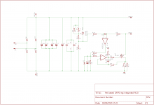
This leaves me with the initial offer, i have two pcb's left of the supply from post #1 those i can supply for postage to anyone who is willing to put in the effort for a stability analysis on the supply. Particularly the CCS part as driving a mosfet with significant miller is challenging. If you read my previous posts i have "fixed" this by putting a small value cap between source and gate, but this cap need to be dimensioned properly. An alternative i have thought about is putting this cap between the output and the non inverting input, in this way the gate voltage dV/dT is still limited by how much the opamp can slew with a capacitive load.
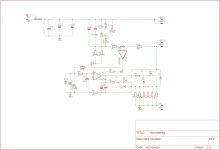
Attached the schematic for reference purposes. and a plot of the board as it stands.
In therms of support, i have sold like 4 kits commercially, and i have send replacement modules to two people. I dont really like email, so most of the times i give people my instant messenger contact information so they can ask questions there. However i want to go a different way: There is nothing in excess of 5+ Amps on the market right now. For instance the highest current version by Tent is 5 Amps.
There is not really a significant market for anything over that, so why don't we do an opensource project? Il provide the design files once something serious is developed on this forum.
I'm suggesting a 2.5V-15V 10A continuous regulator. That needs to meet a dropout requirement of 3VDC at 15A peak current during start-up. (My circuit delivers more current then nominal during startup, but not the 2-3 times the nominal current encountered with traditional AC supplies.
Practical board layout would be similar in topology to my latest board, with MELF 0207 Resistors and SMD parts throughout. Perhaps change over to TO220 sense resistors, and add some LED's to show the module is operating. I could add a comparator to shut everything off if the voltage over the filament rises above that set by the voltage reference. However, this would be primarily caused by output device, or control loop failure. the first is unlikely because these devices are bulletproof if you can keep the heat sink temperature below 70C.
Noise requirement would be 1mV measured with a Fluke 175 or equivalent.
Free from oscillations in the DC to 100Mhz range (checked with a scope)
Long therm stability: within 2000PPM (0.2%) for voltage.
That entails that someone needs to go through the design calculations for loop stability, as I myself rely too much on guestimates and am quite poor at advanced maths although arithmetic is one of my strong points.
If a design is developed that has potential I will then proceed to lay out a PCB for the design. And order these through a separate group buy at 100% markup on purchase price, to recoup costs. Parts could also be ordered through a group buy at a slight markup because.
Some technical ramblings.
Please note: most of what's below is my current understanding of electronics, and might not be entirely accurate.
Allright, the circuit works by comparing the reference voltage referenced to V+ to that of the voltage over the tube heaters. The reference itself is a classical TL431 shunt regulator that can be made adjustable my means of a potentiometer or fixed divider string. I dont know the Impedance of the TL431 in this mode, but i think its below 10 Ohms from DC out to 1Khz. Note that i take 1Khz here as it includes the 4th harmonic of 100Hz? By bypassing this reference with a cap one can lower noise, this is one of the things i added recently.
One possible improvement is to put a LM334 between reference and GND. These have a dropout voltage with a lower limit of 1.5V? this would mean the entire regulator would have 1.5V margin at the 3V dropout requirement from above. They also have a rather high dynamic impedance, so they are far superior to a resistor in therms of AC attenuation. One added benefit is that the reference is operating at a constant current, constant voltage combination. Hence device temperature is independent of supply voltage fluctuations, this presumably is better for long term stability. (this is not entirely true because increase in the supply voltage will cause a ambient temperature rise in most situations)
The CCS is driven through a Low pass filter to set the setpoint of the CCS. The resistor over the cap is to lower the possible voltage on this point (Most opamps dont go directly to ground but several milivolts above that)
There is nothing really to say about the constant current driver. its got a small RC filter on the input to filter out spikes (from ambient) or the harmonics produced by the first comparators switching characteristics. This i would change to 10K /1n later on.
You could theoretically provide for some load on the module by means of a resistor between Heater+ and Heater- so you can adjust the module without a external load resistor. The resistor is inconsequential to the function of the module. except that it creates more waste heat.
Noise rejection is provided by the current source impedance. if this impedance is high from 1Hz to about 1Khz (and beyond) it attenuates the ripple coming from the main filter caps. Think of it this way: A 833 might have a warm resistance of approximately 1Ohm. And the CCS has an impedance of >=1000Ohms in the power supply harmonics range. You are then attenuating the ripple to inaudible levels. Or just run the entire module from a switcher, a friend of mine tried that, in that way you can minimize the dropout voltage to perhaps as low as 2-2.5V. (You kind of want at least 2V over the FET to take advantage of its linear characteristics)
The IXTH80N075L2 has quite flat transfer lines, this means there is less adjustment needed by the opamp to provide for a high impedance CCS. If i remember correctly this means that the early voltage of this device is quite large. This also means that if you have a relatively noise free supply to begin with, you can also reduce the ripple to almost inaudiable levels by virtue of the almost horizontal transfer characteristics of the device.
Final note and an appeal for help from anyone that can SPICE.
This leaves me with the initial offer, i have two pcb's left of the supply from post #1 those i can supply for postage to anyone who is willing to put in the effort for a stability analysis on the supply. Particularly the CCS part as driving a mosfet with significant miller is challenging. If you read my previous posts i have "fixed" this by putting a small value cap between source and gate, but this cap need to be dimensioned properly. An alternative i have thought about is putting this cap between the output and the non inverting input, in this way the gate voltage dV/dT is still limited by how much the opamp can slew with a capacitive load.
Attached the schematic for reference purposes. and a plot of the board as it stands.
Attachments
Last edited:
Some supplementary technical ramblings
I might be worthwile to use the single opamp version of the LM7322 for the constant current source driver. And a LM358 for the comparator, simply because the latter has no vices. Its rock solid in therms of stability, the common mode between the inputs is between GND and VCC-1.5V with no problems. this wont be encountered in most cases, and the diode between non inverting and inverting input keeps this voltage in spec.
Yes it has poor offset voltage characteristics, but you trim those out during initial voltage adjustment. 20uV/C input voltage drift for the worst variant and 200nA input bias variation are entirely acceptable, if you keep the source resistance below 10K. I would have to run the numbers on the complete system in therms of compounding temperature coefficients to calculate whether the 2000K PPM goal for the supply can be met.
Furthermore, you can use the second section as a comparator to drive a two transistor latch to shut the entire thing down during fault conditions.
Or you can quite simply put a BC337 between the opamp output, sense resistors node and GND. to provide for a hardware current limit.
What do mean with "tame them"? Usually that makes me think of oscillation problems but 26s and 45s are not high transconductance tubes.
Sorry that was a figure of speech which may not have come across as intended. I merely wanted to refer to the amount of effort people put into getting the most out of these tubes with filament regulators, regulated B+, chokes etc.
Cool implementation!
Single millivolt RMS noise on your heater is ant fart territory even if you improve it 10 times, the end effect will be astronomically small. To me it sounds likely (gut feeling) that mechanical vibrations, electrical noise etc of an amplifier will drown out anything arising from that 1 mV already.
You sent me some cool pics privately but those were all on high power tubes drawing many amps, did you already try it with some of those vintage low power DHT tubes like the 26 and 45 for example?
Actually i don't really have the equipment to get down in the hair splitting noise, to me its not relevant anyway as factors such as reliability and active protection against fault conditions are much more important.
My digital scope like always shows a HF hash of about 3-4mV but that is due to the fact that i have a budget scope.
Ah Gideon, you are aware of my agreement with a third party about a different version of this circuit for those types. That circuit is much more elaborate, and is meant to be built like a tank and assumes the end user has no knowledge about the handling of electronics besides plus and minus and flipping a switch 😀 So i put in all the protection features you could wish for.
Last edited:
So i put in all the protection features you could wish for.
I need one that stops me from putting my paws onto fully charged caps if you remember me messing with that tube based voltage regulator of yours a while ago. 😀
Once I finally manage to finish my pushpull amp I'll let you know because my next project will have to be some big DHT goodness. This seems like a cool way to get the heaters glowing
Oh i did, you wont do that twice now. 😉
Im currently thinking amongst the lines of replacing the LM7322 altogether with a LM358 and buffering the output with a LH0002. I know the IC is hard to obtain outside of Chinese pulls but i haven't had a DUD in a pull yet.
I would then add a small integration capacitor of say 10n between output and the inverting input.
If push comes to shove i can replace the LH0002 by discretes, this is just more soldering work... Perhaps design around some of those nice low VCEsat transistors from Zetex?
I would then add a small integration capacitor of say 10n between output and the inverting input.
If push comes to shove i can replace the LH0002 by discretes, this is just more soldering work... Perhaps design around some of those nice low VCEsat transistors from Zetex?
V2.0
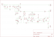
Ive implemented the last changes into a semi complete schematic.
The board will be through hole, so any possible builders dont have to stock up on expensive MELF resistors. Allthrough i like those a lot and they solder faster than their normal 0207 through hole counterparts.
I added a LH0002 buffer because i know from testing this has a good square wave response in a dynamic load setting, hence its expected to be stable, whereas for the LM7322 i can never be sure, because the spice model doesn't seem to exist. Furthermore the 358 is easy to model in spice.
There are some open positions for different bootstrap capacitors. I retained the RC filter on the input of the CCS opamp because it cant hurt, dV/dt on that node is so low that it doesn't do anything but filter out potential HF noise.
I made a model for a TO220 resistor and added that, its likely going to be a 68mOhm part. Or a 100mOhm part with a 1.5V zener, whichever is cheaper. Those resistors are specced for 30W and the 0R1 part could potentially see 22.5W during start up of the regulator.
Normal dissipation with a 10A load = 10A*10A *0.1R = 10W Add about 2-4V over the Fet's and you are at 30-50W. All through the regulator should be capable of running at a dropout of approximately 2V. Leaving you with the option of running from rectified 12V.
Two parallel DO201 diodes where also added to the input, so any monkey mistake in polarity will blow out the fuses rather than take out the opamp.
Leaving those out would mean that if a load was connected, the load would see nearly the entire supply voltage, due to conduction through R1 and the body diodes of the FET's.
Further improvements:
I dislike the parallel devices. using this device for the fet:
IXTN240N075L2 IXYS | Discrete Semiconductor Products | DigiKey
A version that is expandable to well over 15A could be built.
I'm gonna look for a cheap 227 package device with linear characteristics, as i know these are mostly ancient devices that have good DC handling characteristics anyway. EDIT this one looks interesting : IXFN180N25T IXYS - Module | enkele transistor; 250V; 168A; SOT227B; Ugs: +-30V; Idm: 500A | TME - Elektronische Componenten
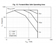
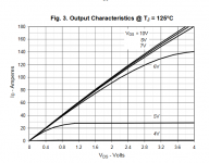
It has lower miller and drive requirements then the TO247 device ive specified earlier. PN for reference : IXTH80N075L2
Ive added both the SOA curves and the transfer characteristics, note that the characteristics at 10-20A are flat from VDS=1V onwards.
And this device for the sense resistor: https://nl.farnell.com/vishay/rtop200vr100jb/resistor-200w-0r1/dp/1141559
The above parts could be used to build a 20-30A version, One needs to add press fit screw terminals in that case. And the input protection diode needs to be 227 as well. Those are around €12 including VAT.
That zener for setting the maximum current is quite unreliable in therms of voltage tolerance. One could add a LM336-1.2 instead, those are inexpensive
If there is any space left over, i am going to look at implementing a crowbar protection circuit.
Please feel free to comment, i know a 20A version is likely only needed by ~10 people worldwide. but it makes a fun entry for me into higher power electronics. And from my experience in repairing welding equiptment (DC Choppers for 400A) I know what a board like that needs in therms of layout.
* Press fit connectors for the in and out M5 pressfit.
* 75um copper thickness board.
* Planes for the entire in output.
* board about 6x4In or 150x100mm
Ive implemented the last changes into a semi complete schematic.
The board will be through hole, so any possible builders dont have to stock up on expensive MELF resistors. Allthrough i like those a lot and they solder faster than their normal 0207 through hole counterparts.
I added a LH0002 buffer because i know from testing this has a good square wave response in a dynamic load setting, hence its expected to be stable, whereas for the LM7322 i can never be sure, because the spice model doesn't seem to exist. Furthermore the 358 is easy to model in spice.
There are some open positions for different bootstrap capacitors. I retained the RC filter on the input of the CCS opamp because it cant hurt, dV/dt on that node is so low that it doesn't do anything but filter out potential HF noise.
I made a model for a TO220 resistor and added that, its likely going to be a 68mOhm part. Or a 100mOhm part with a 1.5V zener, whichever is cheaper. Those resistors are specced for 30W and the 0R1 part could potentially see 22.5W during start up of the regulator.
Normal dissipation with a 10A load = 10A*10A *0.1R = 10W Add about 2-4V over the Fet's and you are at 30-50W. All through the regulator should be capable of running at a dropout of approximately 2V. Leaving you with the option of running from rectified 12V.
Two parallel DO201 diodes where also added to the input, so any monkey mistake in polarity will blow out the fuses rather than take out the opamp.
Leaving those out would mean that if a load was connected, the load would see nearly the entire supply voltage, due to conduction through R1 and the body diodes of the FET's.
Further improvements:
I dislike the parallel devices. using this device for the fet:
IXTN240N075L2 IXYS | Discrete Semiconductor Products | DigiKey
A version that is expandable to well over 15A could be built.
I'm gonna look for a cheap 227 package device with linear characteristics, as i know these are mostly ancient devices that have good DC handling characteristics anyway. EDIT this one looks interesting : IXFN180N25T IXYS - Module | enkele transistor; 250V; 168A; SOT227B; Ugs: +-30V; Idm: 500A | TME - Elektronische Componenten
It has lower miller and drive requirements then the TO247 device ive specified earlier. PN for reference : IXTH80N075L2
Ive added both the SOA curves and the transfer characteristics, note that the characteristics at 10-20A are flat from VDS=1V onwards.
And this device for the sense resistor: https://nl.farnell.com/vishay/rtop200vr100jb/resistor-200w-0r1/dp/1141559
The above parts could be used to build a 20-30A version, One needs to add press fit screw terminals in that case. And the input protection diode needs to be 227 as well. Those are around €12 including VAT.
That zener for setting the maximum current is quite unreliable in therms of voltage tolerance. One could add a LM336-1.2 instead, those are inexpensive
If there is any space left over, i am going to look at implementing a crowbar protection circuit.
Please feel free to comment, i know a 20A version is likely only needed by ~10 people worldwide. but it makes a fun entry for me into higher power electronics. And from my experience in repairing welding equiptment (DC Choppers for 400A) I know what a board like that needs in therms of layout.
* Press fit connectors for the in and out M5 pressfit.
* 75um copper thickness board.
* Planes for the entire in output.
* board about 6x4In or 150x100mm
Attachments
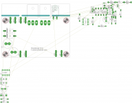
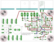
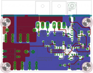
Layout V2.0 nearly finished
Heres the layout of V2.0 in Through hole, its nearly finished. I do have some space left over.
I havent drawn the planes for the high current paths yet.
Any thoughts?
If anyone wants the EDA files onces completed send me your dropbox email through a PM and i will add you to the map.
Heres the layout of V2.0 in Through hole, its nearly finished. I do have some space left over.
I havent drawn the planes for the high current paths yet.
Any thoughts?
If anyone wants the EDA files onces completed send me your dropbox email through a PM and i will add you to the map.
Attachments
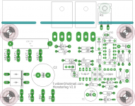
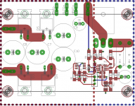
Layout Finished
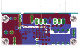
Heres the final layout for V2.0 This is the version i'm going to order, as i prefer this one over the V1.0
Theres a little error regarding the resistor on the top left corner, but i dont have space to move it out of the way, or increase the board over 80x100mm
These boards run about €9 each, anyone want to take a chance on this design? I will have two spares after one proto and two complete boards for someone else. I expect the design to work.
Attachments
Some measurements on the little 2.5A version
I got some feedback on the little 2.5A version i built, one of the points was that during startup the voltage could rise beyond the set voltage by a volt or so depending on the tube used. This was due to the RC time being in the vicinity of 5s for that version. This was due to the fact that the loop upregulates the current at startup to provide quicker heat up time. 4.2A for the 2.5A version. However the tube warms up quicker then the time needed to down regulate the current again, hence the voltage spikes about a volt or more depending on tube thermodynamics. I suspected this might be an issue, but i didnt have any DHT's to test with so i did my initial test with an EL34. I took a 5R4 as substitute for this test.
Decreasing the RC time to 2s flat fixed the overshoot issue during startup, this version needs some component values changed. The two RC resistors are now 47K and the timing capacitor 100uF. I will upload a changed schematic later.
Edit out of caution i will use 47uF and two 47K instead. that brings the -3db point for the low pass filter down to about 1Hz
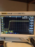
See attached a photo of my RIGOL 1054Z in one shot at 1V/DIV and 1s/DIV. VIN on the regulator is 10V Vout set at 5.0V and loop current limit is 4.2A (1V/.235R)
PS: I can make the gerbers available if you PM me. you should be able to get about 10 boards for under 25 US shipped from China with most board houses. for standard 35um copper boards. 70um seems to carry a hefty premium and the MK1 eyeball says that 35 should be enough to carry the current(10A)
I can also make the single FET version available to anyone that wants it.
And the little version of this regulator.
I got some feedback on the little 2.5A version i built, one of the points was that during startup the voltage could rise beyond the set voltage by a volt or so depending on the tube used. This was due to the RC time being in the vicinity of 5s for that version. This was due to the fact that the loop upregulates the current at startup to provide quicker heat up time. 4.2A for the 2.5A version. However the tube warms up quicker then the time needed to down regulate the current again, hence the voltage spikes about a volt or more depending on tube thermodynamics. I suspected this might be an issue, but i didnt have any DHT's to test with so i did my initial test with an EL34. I took a 5R4 as substitute for this test.
Decreasing the RC time to 2s flat fixed the overshoot issue during startup, this version needs some component values changed. The two RC resistors are now 47K and the timing capacitor 100uF. I will upload a changed schematic later.
Edit out of caution i will use 47uF and two 47K instead. that brings the -3db point for the low pass filter down to about 1Hz
See attached a photo of my RIGOL 1054Z in one shot at 1V/DIV and 1s/DIV. VIN on the regulator is 10V Vout set at 5.0V and loop current limit is 4.2A (1V/.235R)
PS: I can make the gerbers available if you PM me. you should be able to get about 10 boards for under 25 US shipped from China with most board houses. for standard 35um copper boards. 70um seems to carry a hefty premium and the MK1 eyeball says that 35 should be enough to carry the current(10A)
I can also make the single FET version available to anyone that wants it.
And the little version of this regulator.
Attachments
Last edited:
I crunched the numbers on the 833A version once again, and came to the conclusion it can be done with a 12.5V 15+Ampere transformer. And my number crunching also indicates its possible for this supply to use a single Fet as opposed to a double FET version. Provided you use low VF Schottky diodes.
if we assume a mean voltage of 12VDC plus 1.5VRMS ripple, and 10.0V output. the nominal dissipation is: 35W and the +10% Line dissipation is. 48.5W, which is within the limits for a single mosfet. especially given that about 5W is dissipated in the 50mOhm sense resistor.
If you're smart about it you just buy some 12VDC switchmode supplies that can be set to 13V output, and wont mind a 15A surge during heat up.
A suitable heatsink would be around 1K/W. There is a heatsink im eyeing for this purpose.
Possibly more to follow.
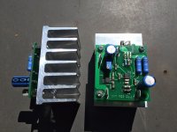
This is what i came up with, i reverted back to through hole resistors for the sense resistors, because 100mOhm 3W MOX types exist, those will however need stand-offs around the legs for better cooling.
I made this design for a 78x100x40mm 1K/W heatsink sold by TME.
Its my tried and tested GM70 regulator on a 1K/W heatsink with on board rectification. The needed capacitors, around 10000uF 16V for 10A are available in the form of 7.5RM. There are connections for using an external capacitor can as well.
I'm gonna order this board in 70uM copper.
Attachments
Dont have the cash for metal plates. I made a smaller version of this regulator for GM70
This ones supposed to work with 833”s the Fet is capable of doing so at 10A up to 6V dropout on a 1K/W heatsink.
This ones supposed to work with 833”s the Fet is capable of doing so at 10A up to 6V dropout on a 1K/W heatsink.
I ordered boards for the last version i posted, if anyone is interested i have three pairs that are surplus to my needs. €10 per pair ex postage. ROHS-ENIG boards in matte black.
I'd say thats a good point, but grab em while they are cheap.
Here are the Gerbers for the PCB's above. The heatsink is a RAD-A5723/100 the FET is a IXTH80n075L2
Here are the Gerbers for the PCB's above. The heatsink is a RAD-A5723/100 the FET is a IXTH80n075L2
Attachments
Last edited:
- Home
- Amplifiers
- Tubes / Valves
- New DHT heater, any need for a 10A+ version?