hi everyone
im having trouble researching what the affect of enlarging the conducting surfaces on speaker terminals would be, all of my google searches seem to focus on "capacitance of wire conductor" or "capacitors"(the actual component).
i'd like to know
(1what would be the affect of enlarging the surface area of the conductor ? pro's & con's
(2 would this potentially create a capacitor ? eg 2 large conductive plates separated by a small air gap.
(3 would the mass of the terminal affect the potential capacitance? larger terminal= more capacitance?
(4 could the shape of the terminal also have an affect ?
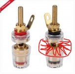
i have included a picture with a "poorly" drawn representation of what i'm trying to describe.
if you know the answers to any of these questions or could point me to some online resources that may help, i would be most grateful.
gaz
im having trouble researching what the affect of enlarging the conducting surfaces on speaker terminals would be, all of my google searches seem to focus on "capacitance of wire conductor" or "capacitors"(the actual component).
i'd like to know
(1what would be the affect of enlarging the surface area of the conductor ? pro's & con's
(2 would this potentially create a capacitor ? eg 2 large conductive plates separated by a small air gap.
(3 would the mass of the terminal affect the potential capacitance? larger terminal= more capacitance?
(4 could the shape of the terminal also have an affect ?
i have included a picture with a "poorly" drawn representation of what i'm trying to describe.
if you know the answers to any of these questions or could point me to some online resources that may help, i would be most grateful.
gaz
Attachments
Pieces of metal that are all shorted together do not make capacitance. The gap between two pieces of metal and the DF of what material fills the gap makes a capacitor. DF is dissipation factor.
I don't quite see the point of more surface area. Speakers rarely draw more than 50 amps and that is adequately carried by 10 ga wire. 2.5 mm. My PV-1.3k can put out 55 A at the 2 ohm rating and they used dual banana jack/binder terminals. I don't own any 2 ohm 650 W speakers however, only 8 ohm 300 W.
Welders can sometimes put out more than 300 amps and there are a special type of terminals for the 0 to 000 ga wire they use to carry those currents. Those do have more area.
I have trouble getting 10 ga wire to go through the hole in the binder terminal, and personally solve that problem by crimping on spade lugs then putting the spade lug under the binder terminal cap. Warning imitation crimp terminals from ***** can melt out at 30 A and above. Use genuine terminals from TE connectivity, Ideal, T&B, Panduit, 3M, or at worst Dorman. Use a crimp tool from Klein or Ideal for best oxygen exclusion of the wire mass.
There are crimp terminals that accept 6 ga wire or another series that accept 0 ga or bigger, but those crimp tools cost in the area of $120 to $200. Check an auto supply for 6 to 8 ga terminals and a welding supply for the 0 to 000 terminals. The crimp tools are hard to find. farnell may have the smaller ones. We made the 1000 A cables for starting diesel truck engines with terminals & a crimp tool from the truck parts supply.
The pressure the binder terminals puts on the crimp terminal has a lot to do with eliminating heat at the higher currents. Hand tightened terminals as shown have marginal torque for 30 A or above currents. At the higher currents 50 A & above hex nuts of brass and brass washers are usually used on a brass stud. 5/16" diameter or 8 mm is usually adequate to 300 A. Above 3/8" brass. There are sources of the insulators that keep the stud from touching the metal case, but I've only seen them in products (as a 50 A DC power supply), not for sale at distributors.
Last edited:
hi jo
the reason i was thinking that more surface area may be better is, that electrons always look for the "easiest path" like water, so why not give them more surface area with which to flow. also by having a larger conducting area you would not need to attach/crimp anything to the wire and you would not need to try and make fat cables fit into the small hole on the terminal/binding post.
are you aware of any research regards this specific subject ?.
gaz
With all due respect, I think you are a bit obsessed/worried with something that really isn't an issue in consumer audio products.
As indianajo has mentioned, connections and wire size are already sufficient for such things as speaker connectors.
Some of this "worry" is due to the internet spreading around all sorts of myths and hype, causing others to pick apart something that isn't really there, nor would make any difference.
Yet, people are told that those "fat wires" are better to use - another internet myth, designed to sell products to the uneducated masses.
For instance, take a close look at a standard 15 amp glass fuse, and notice the fuse wire size inside of it.
It's designed to handle up to 15 amps before failing.
It's also not anywhere near the conducting area of the average 16 gauge zip cord used for speaker wire.
Worrying about those little electrons is silly.
Last edited by a moderator:
I always look for terminals with the least amount of metal, like the Eichman or WBT NextGen at the high end, at the other end, it is often the case that cheaper terminals with plastic nuts are better than pricier ones.
Keep n mind that the electrons flow on the outside of the conductor, how much so depending on frequency. Keeping conductors skinny forces a more uniform charge distribution.
The other question is, how much current do you have to transport across the wire/terminals.
dave
Keep n mind that the electrons flow on the outside of the conductor, how much so depending on frequency. Keeping conductors skinny forces a more uniform charge distribution.
The other question is, how much current do you have to transport across the wire/terminals.
dave
Yet, people are told that those "fat wires" are better to use - another internet myth, designed to sell products to the uneducated masses.
I typically use solid core 24g speaker wire, i do keep them relatively short.
dave
thank you all for your replies to my questions.
i get that large voltage can flow through a small conductor but, what about resistance of said conductor ??
do you guys know of any research that covers this subject ?
i get that large voltage can flow through a small conductor but, what about resistance of said conductor ??
do you guys know of any research that covers this subject ?
Last edited:
AMP (now TE connectivity) did research on the deterioration of connection resistance due to copper oxide on surfaces. A typical binder post on bare wire has many exposed surfaces on the strands which eventually oxidize & gain resistivity. The AMP crimp connector uses the pressure of a binder ring and a tool to meld the strands of a wire into a solid mass, that will not allow the entrance of oxygen. Hence all high current applications as welders & diesel starters use crimp terminals on the ends of the wire. See the AMP application notes that started the whole crimp terminal industry in the 1950's.hi jo
also by having a larger conducting area you would not need to attach/crimp anything to the wire and you would not need to try and make fat cables fit into the small hole on the terminal/binding post.
are you aware of any research regards this specific subject ?.
gaz
The flat surface of a crimp terminal, under a washer & nut, also has no entry point for oxygen. We found crimped wires under screw terminals allowed reliable passage of low energy signals in the factory test systems for decades. OTOH the replacements, punch blocks, were only reliable under telephone conditions, that is voltages >48 and currents over 50 ma.
The metals that don't oxidize, gold, palladium & rhodium, are useful for low current connections to avoid oxide intrusion. However these metals melt out at high currents and are not useful over 100 ma. Pressure of a brass or tin plate nut & washer or a plated crimp ring is the cheapest device to exclude oxygen intrusion at high currents. Then there is always solder, which totally excludes oxygen, but can melt out at high currents. Solder has been banned in building wiring since the 50's for that reason, solder melt out at currents over ~5 amps can start building fires.
BTW, I hear less vibrato on top octave piano tracks with 8' of 10 ga wire to my speaker, as compared to 20 ' of 16 ga zip cord. As pianos are not equipped with vibrato, I view this sound from the 16 ga zip cord as distortion. Your results may vary. I'm a highly experienced amature musician sensitive to incorrect pitch. The effect may be limited to this amp/speaker combination. I fished the 10 ga 3SO cord out of the factory dumpster, so I didn't pay $$$ to some snake oil salesman. I had spade lugs crimped on the amplifier end and 1/4 phone plugs soldered on the speaker end.
Last edited:
thank you all for your replies to my questions.
i get that large voltage can flow through a small conductor but, what about resistance of said conductor ??
do you guys know of any research that covers this subject ?
Using typical 16 gauge stranded copper speaker wire, the actual resistance of it is about 0.005 ohms per meter - absolutely nothing worth worrying about.
There is a point of minimal improvement with speaker wires.
You do need a decent connection - that can be provided with most 4mm screw posts.
You do need a decent wire - that can be provided with 2.5mm twin core.
Gold plating is often used so that oxides don't interfere with the connections.
You do need a decent connection - that can be provided with most 4mm screw posts.
You do need a decent wire - that can be provided with 2.5mm twin core.
Gold plating is often used so that oxides don't interfere with the connections.
Last edited:
When it REALLY matters: you do NOT want an over-sized contact area. A major factor in connections is tarnish. Oxidized copper is a poor conductor. You want enough tons per square foot to crush through the oxide to get a metal on metal joint.
Gold is pretty, but does not solve the tarnish on the wire. If you have enough contact pressure to bite the wire, the tarnish on the connector gets bitten-through also. Nevertheless it is common to coat connectors with tim-like material so they do not turn green in the store.
You are now thinking gold wire on gold connectors. Gold is a terrible conductor for its diameter, and stupidly expensive for conductivity. Yes I know people tear-out good copper and route tiny gold wire "for better sound". I think wine is a better sonic investment.
When it REALLY matters: you do NOT want an over-sized contact area. A major factor in connections is tarnish. Oxidized copper is a poor conductor. You want enough tons per square foot to crush through the oxide to get a metal on metal joint.
Gold is pretty, but does not solve the tarnish on the wire. If you have enough contact pressure to bite the wire, the tarnish on the connector gets bitten-through also. Nevertheless it is common to coat connectors with tim-like material so they do not turn green in the store.
You are now thinking gold wire on gold connectors. Gold is a terrible conductor for its diameter, and stupidly expensive for conductivity. Yes I know people tear-out good copper and route tiny gold wire "for better sound". I think wine is a better sonic investment.
And after listening to many opinions about wire, copper, coathangers, silver, and gold, I tend to hit the wine bottle to soothe my nerves too.
Bottom line, good old copper wire, ya can't beat it.
When I installed my system, using 16 gauge "zip cord", I get out the soldering iron and tin the stripped ends to prevent the strands from fraying, and it assures a good non-corroding connection.
If it works for me, it'll work for everybody. 😉
At the impedance levels of speaker connections all that matters is the end-to-end resistance, which will be 99% down to the wire itself, unless the connection is loose or corroded!hi everyone
im having trouble researching what the affect of enlarging the conducting surfaces on speaker terminals would be
A few picofarads of extra capacitance is about 7 orders of magnitude higher impedance than the speakers themselves.
Avoid iron/steel for high current audio signals though, this can create measurable distortion due to the non-linear inductance of magnetic materials. There are a lot of cheap brass- and gold-plated steel connectors out there alas.
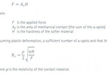
@PRR (contact pressure!!!) i have just spent a number of hours reading about exactly what you have just stated. surface area is not as important as contact pressure it seems. if you know the (real world) ratio of contact pressure to resistance please share, so far i've found this calculation( see pic ) which is way beyond my maths skills and requires measurements that i cannot obtain.
@Mark T
"At the impedance levels of speaker connections all that matters is the end-to-end resistance, which will be 99% down to the wire itself,"
what about the banana plugs or fork connector and solder, surly they add more resistance than a short run of pure copper wire.
gaz
@Mark T
"At the impedance levels of speaker connections all that matters is the end-to-end resistance, which will be 99% down to the wire itself,"
what about the banana plugs or fork connector and solder, surly they add more resistance than a short run of pure copper wire.
gaz
Attachments
I use banana plugs because I can't easily get to the backs of my amps. Also I change equipment and trying to poke bare wires into tiny invisible holes is not my idea of fun. Least metal usually means Z-plugs, but if not, then one piece of metal without joints is my preference. Gold (or even rhodium, if being re-plugged very often) plating limits corrosion at the contact point.what about the banana plugs or fork connector and solder, surly they add more resistance than a short run of pure copper wire.
Applying pressure flattens the surface increasing the contact area and reducing resistance.surface area is not as important as contact pressure it seems.
https://materion.com/-/media/files/...e-no-06---the-importance-of-contact-force.pdf
Attachments

Hello,
In our company sometimes there are power supply issues with machines using a LOT of current like professional welding machines. The complete electrical system is installed by professional with components that passed several test ( because of insurance) .
Most of the time problems are caused by connectors '' loosing grip '' on the cable and because of immense currents they will get hot. So i think most of the resistance is in the connector.
Today i looked for some spades. I am using the bare copper Cardas binding post which are very nice. My idea was to find bare copper spades which could need some cleaning once in a while. I am using the original flatline from 25/30 years ago so no need for a big spade that can accept a massive wire. I wonder how these can be soldered with a real good joining?? Because i am in the metal business so to say and i have worked with copper before i thought why not make my own kind of spade from a flat piece of copper 1,5 mm thickness by means of cnc punching or laser cutting. On the side where there is usually a kind of tube to receive the cable i can create a kind of rectangular space by bending to create a space just big enough to enter the cable and solder it properly.
Greetings, Eduard
what about the banana plugs or fork connector and solder, surly they add more resistance than a short run of pure copper wire.
gaz
If you're talking about consumer audio equipment, the resistances and associated voltages and currents involved in the connectors you're asking about is negligable, and certainly nothing to worry about.
Others may "nit pick" on the subject, but that only shows how little they understand about such things.
It's sort of like debating about a grain of sand on the beach and how it might affect the whole beach.
@awkward i currently use forks
@galu hay galu, hope your well. i read an article earlier today with a similar diagram, explaining the importance of a-spots
@eduard there are guys on here with way more knowledge than me who may tell you to do it differently, but if it were me, i'd tightly crimp the spade/fork connectors to the wire and then solder them with 4%Ag solder.
@wise i get that its over kill for home audio, but i'm just trying to understand how to achieve the best possible results, and if you can improve something then why not?
gaz
- Home
- Design & Build
- Parts
- questions about terminals