Happy to hear you now have that working.
Don't forget to post some pics of the amp when you're done.
Don't forget to post some pics of the amp when you're done.

Nice looking build! Perfect size chassis too
Thank you CodyT.
4u Chassis I think.
Next time I buy a pcb from the store.
I’ll have to double check the parts aren’t unobtainable.
4u Chassis I think.
Next time I buy a pcb from the store.
I’ll have to double check the parts aren’t unobtainable.
Ok rather than read all 400+ pages on this thread, can someone get me up to speed what I would be looking at building this amp? I have purchased a kit from a person that didn't have the time to built it so want to verify what I need. Photos of what I recieved:


1) What version PCB do I have as it seems Mr Pass has done v2 of the VFET or revisions / additions. As shown in my photo I have CSX1SONY VFET printed on the PCB. The DIY online shop has PCB that look different to mine: Sony VFET PCBs – diyAudio Store
- what compromise on the differences?
2) The original owner appeared to have mounted the VFETs on the heatsink T-bar. Also marked on one of the VFETs is a black marking. The seller sold them in good faith so should I be concerned if they were damaged or not working? They have solder on the pins. Easy method of testing them?
3) On the PCB I noticed there's input printing XLR- and XLR+, can this amplifier be run in balanced mode from pre-amps that have balanced outputs? I don't recall any readings about this. On the PCB has Jensen line transformer JT-123-FLPCH and JT-112-LCF (difference?)
4) Is the power supply suitable enough on board and all that I need is to wire in +32V AC ? Toroidal?
5) Lastly, is there a parts list for this PCB? Mouser or Digikey to buy all the components?
Excuse my ignorance as I haven't had time to fully search and find info what's needed. Any worthy info such as chassis design etc. would be grateful.
Look at the group buy
PCBPCBs for Nelson Pass‘ CSX1 SONY VFET amplifier
And look at the FVet article on Firstwatt.com look for CX1
PCBPCBs for Nelson Pass‘ CSX1 SONY VFET amplifier
And look at the FVet article on Firstwatt.com look for CX1
Last edited:
Mr Pass published 2 original VFET amps, CSX1 and CSX2. These boards were made for CSX1. The DIYAudio VFet was a separate, special effort by Mr Pass to provide kit with boards, T mounts, and matched VFets. No longer available. This thread is about the last kit.
CSX1... this board was purchased in a group buy, sadly created by a member who is no longer with us.
No BOM
There is provision for the Jensen input transformer to use either pins, or wires, thus the 2 different specifications.
He also set up the board to use either XLR or RCA inputs. Using a jumper to make the choice.
Be sure to look at Mr Pass’ article, the power supply is rather complicated, for a FW amplifier. If I recall correctly, some, but not all, of the regulation circuit was on the boards. And it is much more than just hooking up a power transformer.
@Super_BQ: Here's the article for reference:
http://www.firstwatt.com/pdf/art_sony_vfet_pt1.pdf
As Bones13 mentioned, the power supply for CSX1 is more complicated that the
usual FW one.
For testing, you might want to try this schematics from post #209:
https://www.diyaudio.com/forums/pass-labs/276711-sony-vfet-amplifier-2-a-21.html#post4392065
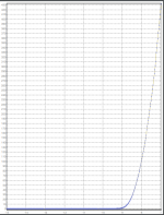
It looks like one of your 2sk82 has the marking. Try wiring up the circuit for 2sk82
with the vfet heat sinked and start with the pot adjusted so the gate voltage is at -19V.
Monitor the voltage across the 1 ohm resistor for current. At -19V you shouldn't
see current. Gradually increase the gate voltage (moving towards zero) at some
point you the VFET should start conducting. See if you can gradually
increase the current to say 0.5A.
The current to gate voltage should follow a curve like the sample
attached.
http://www.firstwatt.com/pdf/art_sony_vfet_pt1.pdf
As Bones13 mentioned, the power supply for CSX1 is more complicated that the
usual FW one.
For testing, you might want to try this schematics from post #209:
https://www.diyaudio.com/forums/pass-labs/276711-sony-vfet-amplifier-2-a-21.html#post4392065
It looks like one of your 2sk82 has the marking. Try wiring up the circuit for 2sk82
with the vfet heat sinked and start with the pot adjusted so the gate voltage is at -19V.
Monitor the voltage across the 1 ohm resistor for current. At -19V you shouldn't
see current. Gradually increase the gate voltage (moving towards zero) at some
point you the VFET should start conducting. See if you can gradually
increase the current to say 0.5A.
The current to gate voltage should follow a curve like the sample
attached.
Attachments
This is the Permaneder R.I.P. member that design the first PCB, I have the same, this board has all the parts, including the regulators and the buffer behind the transformer.
Is fantastic, so wide and easy to build.
Is fantastic, so wide and easy to build.
Can someone tell me if SK60/SJ18 from SONY TA-4650 can be used for VFET amp ?
I have collected the VFET board from diystore and everything except for the VFET transistors. I'm currently bidding on Sony TA-4650 but not sure if SK60/SJ18 in place of the SK82/SJ28 as listed in the PASS Vfet schematic.
If it can be used, do i have to adjust the bias, resistors, caps, or voltage rail higher/lower for Sk60/SJ18 ? Anything i need to look for if Sk60/SJ28 are used ?
Thanks,
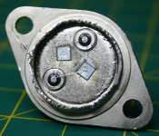
Well rumor has it that the 2SK60/2SJ18 (single die) are exactly half a 2SK82/2SJ28 (twin die). The electrical data suggests the same.
The attached pics show the internals of a 2SK82 and a 2SJ18.
I suppose you could build the amp with half the bias current using the 2SK60/2SJ18, giving you about half the output power.
The attached pics show the internals of a 2SK82 and a 2SJ18.
I suppose you could build the amp with half the bias current using the 2SK60/2SJ18, giving you about half the output power.
Attachments

Well rumor has it that the 2SK60/2SJ18 (single die) are exactly half a 2SK82/2SJ28 (twin die). The electrical data suggests the same.
I suppose you could build the amp with half the bias current using the 2SK60/2SJ18, giving you about half the output power.
I believe just lower Iq for, say, 30% and you're good
Ahh i see, thank you Rodeodave and ZM, so 2sk60/2sj18 are exact drop-in replacement for 2sk82/2sj28 since they have the exact same pin out, the only caveat is lowering Iq to 30% to 50% as they only have single die vs dual die as in 2sk82/2sj28
Thank you so much for the prompt replies and advices.
-TD
Anyone have an idea if these are legit?
1pair Audio Transistor SONY TO-3 2SJ18/2SK60 J18/K60 100% Genuine and New | eBay
1pair Audio Transistor SONY TO-3 2SJ18/2SK60 J18/K60 100% Genuine and New | eBay
Short answer - no!Anyone have an idea if these are legit?
1pair Audio Transistor SONY TO-3 2SJ18/2SK60 J18/K60 100% Genuine and New | eBay
- Home
- Amplifiers
- Pass Labs
- Sony vFET Amplifier Part 2