Afternoon all,
I'm embarking on a lockdown project to convert an old Marshall solid state amp into a Vibrochamp style valve combo.
I've made a few changes to the circuit. Partly to tailor the tone to my tastes, partly as an attempt to improve some elements of the circuit which look a little dated by modern standards, but mainly to suit the spare parts I have to hand.
I was hoping for some advice on the layout of the amp. I've stuck pretty closely to the original component layout, so I would hope not to run into any major problems. Does anything about my layout leap out as problematic, or just plain wrong?
I'm particularly interested in keeping the noise as low as possible, to which end I've added extra filtering in power supply, and a further extra stage on the preamp valve.
Chassis space is tight, but I think I have all the major components organised logically, with the exception of the OT.
The logical place would seem to be in line with the power transformer and valves but 90 degrees off axis, at the opposite end of the chassis. Is it a good idea to have the OT so close to the input valve?
Alternatively, I could bolt it to the cabinet somewhere, but that would necessitate longer leads than ideal.
Finally, I'm using a bus bar for the zero volt signal return. What is the best place to connect this to the chassis?
Thanks for looking,
Matt.
Ps. Not shown on the diagram, AC enters on the back panel by the PT, On/Off and standby switches on the front panel opposite, with a solid state bridge rectifier mounted in between, in line with the reservior caps.
Attachments
IMO, it's a very bad idea. There are absolutely enormous signals on the primary side of the OT, easily up to 600 volts peak to peak with the amp running flat out and a 350V B+. The wires running from the output valve anodes to the transformer primary will radiate that enormous signal into the air, and if the input valve picks it up through stray capacitance (because the wires are in the same vicinity as the input), you will have major problems with oscillation.Is it a good idea to have the OT so close to the input valve?
Is it an option to move the power supply (power transformer, rectifier, filter cap), to the cabinet, and run the DC output from there to the amp? That might let you move the OT where it belongs, close to the output valve anodes. It's not a good idea to have long wires from output valve anodes to the OT primary, as those wires carry the largest signal swings in the entire amplifier.Alternatively, I could bolt it to the cabinet somewhere, but that would necessitate longer leads than ideal.
You might find Merlin Blecowe's chapter on grounding helpful - it helped me cure a major hum problem a couple of years ago: The Valve WizardFinally, I'm using a bus bar for the zero volt signal return. What is the best place to connect this to the chassis?
-Gnobuddy
Beware that "extra filtering" will also lessen the "sag" feature of small tube amps that adds to their charm. I think increasing the power supply choke value (or adding one if it doesn't have one) will be more effective at lowering hum.I'm particularly interested in keeping the noise as low as possible, to which end I've added extra filtering in power supply
Hi Gnobuddy,
Thanks for the advice.
I had an intuition mounting the OT so close to the sensitive input curcuitry was a no-no - thank you for explaining exactly why. This actually helps explain why an earlier project was a roaring failure. I'd mounted the OT right where I shouldn't, and it did indeed squeal like a highly strung pig 🙂
It's probably not practical to move the PT and associated circuitry into the cab. The PT is a 'top down' affair, salvaged from an old 2-track reel to reel, and needs a chassis to mount to. There is space on the chassis to mount the OT, although not much (I should add, the metal work is already done for the PT and valve locations. I'm using the same chassis as from my previous failed project, and have doomed myself to a flawed layout!). I'll take your advice into account and try and find the best place for the OT on what chassis space I have left...
Regarding grounding, I have a copy of 'Designing Valve Preamps for Guitar', by Merlin Blencowe. The grounding chapter from that book is the one reproduced online. Safe to say most of what I know comes from that book (and the two by Morgan Jones). I'm reasonably confident I've implemented a sound grounding scheme as per his advice. Did you notice anything about my proposed grounding scheme that looked wrong?
To reiterate my previous question - what's the best place to connect the bus bar to the chassis? I've read conflicting advice (from reliable sources) - either at the input jack, the input valve, or at the earth safety bond. Is there a single correct answer, or does it depend on your layout?
Thanks again for the help, apologies for asking more questions.
Matt.
Thanks for the advice.
IMO, it's a very bad idea. There are absolutely enormous signals on the primary side of the OT, easily up to 600 volts peak to peak with the amp running flat out and a 350V B+. The wires running from the output valve anodes to the transformer primary will radiate that enormous signal into the air, and if the input valve picks it up through stray capacitance (because the wires are in the same vicinity as the input), you will have major problems with oscillation.
I had an intuition mounting the OT so close to the sensitive input curcuitry was a no-no - thank you for explaining exactly why. This actually helps explain why an earlier project was a roaring failure. I'd mounted the OT right where I shouldn't, and it did indeed squeal like a highly strung pig 🙂
Is it an option to move the power supply (power transformer, rectifier, filter cap), to the cabinet, and run the DC output from there to the amp? That might let you move the OT where it belongs, close to the output valve anodes. It's not a good idea to have long wires from output valve anodes to the OT primary, as those wires carry the largest signal swings in the entire amplifier.
It's probably not practical to move the PT and associated circuitry into the cab. The PT is a 'top down' affair, salvaged from an old 2-track reel to reel, and needs a chassis to mount to. There is space on the chassis to mount the OT, although not much (I should add, the metal work is already done for the PT and valve locations. I'm using the same chassis as from my previous failed project, and have doomed myself to a flawed layout!). I'll take your advice into account and try and find the best place for the OT on what chassis space I have left...
You might find Merlin Blecowe's chapter on grounding helpful - it helped me cure a major hum problem a couple of years ago: The Valve Wizard
Regarding grounding, I have a copy of 'Designing Valve Preamps for Guitar', by Merlin Blencowe. The grounding chapter from that book is the one reproduced online. Safe to say most of what I know comes from that book (and the two by Morgan Jones). I'm reasonably confident I've implemented a sound grounding scheme as per his advice. Did you notice anything about my proposed grounding scheme that looked wrong?
To reiterate my previous question - what's the best place to connect the bus bar to the chassis? I've read conflicting advice (from reliable sources) - either at the input jack, the input valve, or at the earth safety bond. Is there a single correct answer, or does it depend on your layout?
Thanks again for the help, apologies for asking more questions.
Matt.
Beware that "extra filtering" will also lessen the "sag" feature of small tube amps that adds to their charm. I think increasing the power supply choke value (or adding one if it doesn't have one) will be more effective at lowering hum.
Hi dotneck335,
Thanks for the advice. I'd considered that point, but at the volumes I usually play I'm not generally asking enough of the PT to cause it to sag. Although I occasionally get to crank it up to the sweet spot, I thought the trade off in a stiffer power supply vs. reduced hum was worth it.
I hadn't considered a choke though. It's not practical for me to fit one right now, but I'll look into it as a possible future mod. I can always remove the extra stage of filtering if and when I fit a choke.
All the best,
Matt.
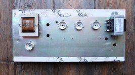
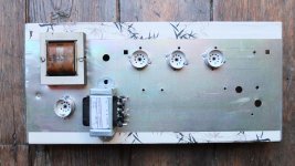
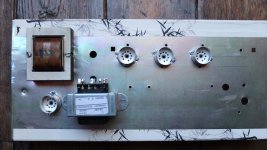
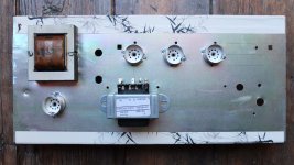
A few thoughts on OT positions...
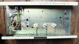
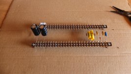
I've attached photos of potential locations for the OT, and a png of the layout, to save the bother of downloading a pdf.
Valve order - from PT outwards - EL84 output valve, ECC83 trem circuit, ECC83 input.
The first location has been proven wrong - both in theory and practice. Do any of the other 3 have merit?
My guess is that the final position - online with the output valve, major axis at 90 degrees, is the most promising?
It's not ideally placed regarding the PT, but perhaps sufficiently off axis and distanced to avoid any major coupling issues...
I guess some practical experimentation is in order at this point 🙂
Edit: I've checked clearance, none of these locations foul the speaker.
Attachments

Last edited:
Those 3 look about the same to me. In every case, the axis of the PT coil is at 90 degrees to the axis of the OT coil. Rotating the transformer about its coil axis usually doesn't do anything, good or bad, so it probably won't make much difference which way you point the lugs on the OT (the variations shown in your last 3 pics).Do any of the other 3 have merit?
-Gnobuddy
Those 3 look about the same to me. In every case, the axis of the PT coil is at 90 degrees to the axis of the OT coil. Rotating the transformer about its coil axis usually doesn't do anything, good or bad, so it probably won't make much difference which way you point the lugs on the OT (the variations shown in your last 3 pics).
-Gnobuddy
Hi again,
I think I follow you... Am I right to visualise the magnetic field from a transformer as roughly a douhgnut shape around it's axis? The strongest part of the field being closest to it's core, diminishing - and perhaps spreading a little - as it moves further away?
In this case, the magnetic field from the PT would be emanating vertically, with regards to the plane of the chassis, whereas the magnetic field from the OT is emanating horizontally. So no matter which way I rotate the OT, it's still radiating it's magnetic field at 90 degrees to the PT?
The best place for the OT then, would be in the last photo, lugs pointing towards the output valve, as close as possible to the output circuitry?
From memory, Morgan Jones cautions against aligning beam tetrodes with output valves, unless their axes are 90 degrees apart. As a pentode, an EL84 shouldn't be so finicky?
Again, I'll try some practical experimantation. Merlin Blencowe recommends (from memory - I'll read the paragraph again before I try it!) hooking up the PT, and connecting the OT to a speaker, then moving the OT around the chassis untill the position of maximum hum rejection is found. I think Morgan Jones suggests the same thing, but hooked up to an oscilloscope - a luxury I do not currently have.
Thanks for the help. Hope I'm following it correctly,
Matt.
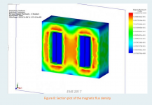
If there was no iron core, it would indeed be a doughnut shape. The iron core modifies that, but without some sophisticated magnetic field modeling, we can only hope it's still some kind of deformed doughnut, with the same axis as before.Am I right to visualise the magnetic field from a transformer as roughly a doughnut shape around it's axis?
The attached image shows a transformer magnetic field simulation done using a popular CAD program called Solidworks. (I didn't do the simulation, I found this on the 'Web.) It shows the "doughnut" idea is still roughly true, except the doughnut has been squashed quite a bit from two sides so that most of it fits into the iron core. This simulation shows no magnetic flux at all outside the core - if only things were this good in real life! 🙂
I have an old Bogen valve amp that has the PT and OT mounted at 45 degrees to each other (not 90 degrees). I assume some engineer tinkered with the transformer orientation at the prototype stage, and found that 45 degrees produced the lowest hum...
Exactly!In this case, the magnetic field from the PT would be emanating vertically, with regards to the plane of the chassis, whereas the magnetic field from the OT is emanating horizontally. So no matter which way I rotate the OT, it's still radiating it's magnetic field at 90 degrees to the PT?
Sounds good!The best place for the OT then, would be in the last photo, lugs pointing towards the output valve, as close as possible to the output circuitry?
One of the key design features of beam tetrodes is that the screen and control grids are aligned, so that the screen grid is in the "shadow" of the control grid wires, and relatively few electrons actually hit the screen grid - they pass between the screen grid wires instead.From memory, Morgan Jones cautions against aligning beam tetrodes with output valves (transformers?), unless their axes are 90 degrees apart. As a pentode, an EL84 shouldn't be so finicky?
If we put a strong magnetic field in the vicinity of the valve, the electron paths get bent into arcs instead of being straight lines - so there is a distinct possibility that a lot more electrons will end up hitting the screen grid wires. That in turn means lots more screen current, followed by an overheated and melted screen grid and a dead valve.
Honestly, I think the enormous permanent magnet in the guitar speaker is the thing most likely to cause problems here. But it can't hurt to try and keep the transformer magnetic fields away, too.
I know that feeling well! I started building electronic things when I was quite young, and didn't have so much as a multimeter (this was before DMMs!) for many, many years....an oscilloscope - a luxury I do not currently have.
I finally bought a digital scope a few years ago. It's wonderful, but in some ways I liked the old analogue scopes better for audio work.
-Gnobuddy
Attachments
Last edited:
I know that feeling well! I started building electronic things when I was quite young, and didn't have so much as a multimeter (this was before DMMs!) for many, many years.
I finally bought a digital scope a few years ago. It's wonderful, but in some ways I liked the old analogue scopes better for audio work.
-Gnobuddy
Hi Gnobuddy,
Thanks for the help. I experimented with the position of the OT whilst hooked up to a speaker. Adjusting by ear, it was happy almost anywhere in the space available, so I put it where it was most convenient with regards the output circuitry.
An oscilloscope would have been handy, to be sure. Adjusting soley by ear feels a little amateur to me at this point - it would have been nice to have some actual data.
Annoyingly, I bought a cheap scope (an old Hitachi from ebay) when I first started getting into electronics about a decade ago. I assumed I'd be using one all the time, but it sat literally gathering dust in the corner of my workshop, so I gave it to a friend.
Naturally, as soon as I didn't have one, I suddenly found a thousand uses for it!
I guess I'll have to bite the bullet before long and re-invest, there's only so much a DMM can tell you (although I'm thankful to own one - don't know how you managed without!).
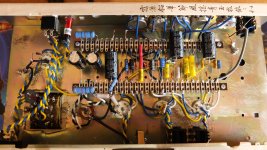
The project is finished now. It was quite a squeeze getting all the components into what is a fairly small chassis, but just about possible. I had to mount the 10K dropping resistor diagonally - which was annoying - but no-on need know...😉
For a single ended amp, hum is very low. It gets a little noisy at full gain, but no worse than a lot of other amps I've owned. This is another area where a scope would be handy. Some actual measurements would be nice. I think I may have crossed a line from worrying about whether the circuit works, to worrying about how well it's performing!
I've attached some pics of the finished project. Just need to find some knobs which will fit the solid metal shafts - nothing in my parts drawer fit.
Thanks again for the help,
Matt.
Attachments


That's pretty much the tragic tale of my packrat life. Hoard all sorts of things that might be useful, finally get rid of them, then find a need for them a week later. 🙂Naturally, as soon as I didn't have one, I suddenly found a thousand uses for it!
Temper-tantrums, occasional tears, and lots of re-working and re-building the same circuit over and over until it worked. Apparently I was a stubborn kid! 😀...don't know how you managed without!
Congratulations!The project is finished now.

No shame in that at all - I think this can be a very useful bit of (slightly) out-of-the-box thinking, and it's good to keep as a tool in your mental box of useful tricks. Electrons really don't care what angle they're flowing at!I had to mount the 10K dropping resistor diagonally...
I once eliminated two wire jumpers, some oddly twisted component leads, and two cuts in the copper traces in a small stripboard prototype carrying a reflective optical sensor chip (LED and phototransistor), simply by twisting the chip about 40 degrees.
I was helping a friend (who made the prototype) to make fifty more of these little boards to be used in the physics lab of a local school. So not having to cut, bend, and solder a 100 jumper wires was quite an advantage!
My friend has a touch of OCD (as so many of us technical types do), so he had to make a bit of an effort to be okay with seeing a sensor rotated at about 35-40 degrees to the edge of the PCB. But he had no trouble recognizing the hours of work saved by doing so!
-Gnobuddy
- Home
- Live Sound
- Instruments and Amps
- Fender Vibrochamp style amp layout advice