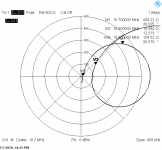
I've played some more with the ceramic filter. I narrowed the span to the more interesting range 10.7MHz+-200KHz and added more markers at +-100 KHz.
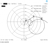
The second plot is calculated port impedance in Ohms + phase angle, calculated from s11. That does not look like a nice linear phase shift vs. frequency.
Now back to this !!"§$%&?=!!! semi-stable preamp.
The second plot is calculated port impedance in Ohms + phase angle, calculated from s11. That does not look like a nice linear phase shift vs. frequency.
Now back to this !!"§$%&?=!!! semi-stable preamp.
Attachments

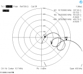
Sorry: I changed the graph parameters for the second set of screenshots (center frequency = 10.7MHz, span 1MHz), as there was nothing interesting elsewhere.I don't get it. In post #8, there was a dip in the transfer around 10.76 MHz for configuration 3, which meant an impedance maximum. You now again get a dip at about the same frequency (slightly lower, 10.73 MHz), but as you have a parallel configuration, this time you need an impedance minimum to get a dip.
I mentioned it, but I should have made it clearer.
Taking this into account, the two sets seem broadly consistent.
There could be minor differences due to the different loading impedances.
I didn't take care about the I/O pins of the filter, but since conf. 3 & 4 are symetrical, this shouldn't matter
Yes, it looks rather disastrous. Which pins of the filter did you measure?I've played some more with the ceramic filter. I narrowed the span to the more interesting range 10.7MHz+-200KHz and added more markers at +-100 KHz.
The second plot is calculated port impedance in Ohms + phase angle, calculated from s11. That does not look like a nice linear phase shift vs. frequency.
Now back to this !!"§$%&?=!!! semi-stable preamp.
Sorry: I changed the graph parameters for the second set of screenshots (center frequency = 10.7MHz, span 1MHz), as there was nothing interesting elsewhere.
I mentioned it, but I should have made it clearer.
Taking this into account, the two sets seem broadly consistent.
There could be minor differences due to the different loading impedances.
I didn't take care about the I/O pins of the filter, but since conf. 3 & 4 are symetrical, this shouldn't matter
You are right, I didn't read your post carefully enough. Configuration 3 looks best again, although the distortion may still be too high.
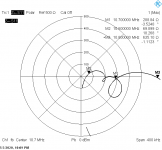
Leaving the other side open (instead of 50 Ohm termination) makes things different, but not better.
How about Elvee's configuration 3? (See post #8, https://www.diyaudio.com/forums/analogue-source/353682-ceramic-resonator-10-7mhz.html#post6186571 )
Last edited:
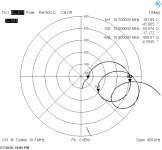
And #3
So just as unusable as the rest; the magnitude of the impedance has the same trends as Elvee measured, but the phase response over the IF channel is nowhere near a straight line segment (not even a monotonic curve).
Exactly. And the center is worst.
One could use it for "Flankendemodulation" in German, when you tuned
the receiver to the falling edge of the passband and demodulate it
in AM style. Not HiFi.
One could use it for "Flankendemodulation" in German, when you tuned
the receiver to the falling edge of the passband and demodulate it
in AM style. Not HiFi.
Yes, it looks rather disastrous. Which pins of the filter did you measure?
pin 1 vs GND
One could use it for "Flankendemodulation" in German, when you tuned
the receiver to the falling edge of the passband and demodulate it
in AM style. Not HiFi.
Indeed. In Dutch that's flankdetectie, and here it was first used for broadcast reception on 6 November 1919 at 8 PM local time. I also haven't a clue what it is called in English.
I listened to a demonstration of a reproduction of a 1920's narrowband FM broadcast transmitter and a genuine 1920's broadcast receiver with flankdetectie in September last year. It sounded better than I expected, even though it certainly wasn't HiFi. YouTube
Anyway, I think the answer to the thread starter's original question is no.
> In Dutch that's flankdetectie, ... I also haven't a clue what it is called in English.
"Slope detection", though "flank detection" would be understood.
Frequency modulation - Wikipedia
"Slope detection", though "flank detection" would be understood.
Frequency modulation - Wikipedia
- Home
- Source & Line
- Analogue Source
- ceramic resonator 10.7MHz