Hi everybody!
I wanted to make another small radio using TA2003P. Because I don't have another 2pin ceramic resonator of 10.7MHz as it is shown at pin 10, I would like to ask you if there is any posibility of either using a 3 pin ceramic filter with the ground coupled together with one pin, and the other one to be free, or using half of a 3 pin ceramic filter of 10.7MHz.
Thank you!
Attachments
I think it should work, but I have no idea whether having the third pin open or connected to the supply works best (the resonator's common pin has to be tied to the supply rather than ground according to the application circuit). It could even be that some resistance between the third pin and the supply works best.
This resonator has a big influence on the distortion. Is there any way you could measure the distortion and see what works best?
This resonator has a big influence on the distortion. Is there any way you could measure the distortion and see what works best?
The 2 pin ceramic resonator appears to work as the quad coil in a quadrature fm detector. I'm not sure a bandpass filter would work in that application. Those ceramic resonators should be readily available, but you might have to buy a box of 20 from a vendor.
The minimum amount on eBay is 10, search for ceramic discriminator. They are different from 3-pin bandpass filters. Their code starts with CDA10.7M...
I don't think so, for the reason given by Ray.I wanted to make another small radio using TA2003P. Because I don't have another 2pin ceramic resonator of 10.7MHz as it is shown at pin 10, I would like to ask you if there is any posibility of either using a 3 pin ceramic filter with the ground coupled together with one pin, and the other one to be free, or using half of a 3 pin ceramic filter of 10.7MHz.
Older circuits, like TBA120 or SO41P having multiple pins for the quadrature detector could use the in/out phaseshift to demodulate, but it didn't work very well, and with a single pin it will be even worse.
I must have a few 3-pin filters somewhere in a drawer, if I can locate them, I will measure their characteristic to see if they can be converted to 2-pin in some way (but I am not too optimistic).
An alternative would be a standard coil+cap tuned circuit (probably series, since it has to replace a resonator)
Attachments
To the best of my knowledge, these three-pin ceramic filters are basically two mechanically coupled resonators, so why would it not work? It might work poorly, though, for example if the bandwidth is too small.
Thank you, but I still have a question: here I found another way of coupling the pins. Can I do this trick with the 10.7MHz 3 pin filter for using it as quadrature detector instead of that 2 pin resonator on FM for this TA2003P?
Simplest 455 KHz Oscillator uses only three parts negative resistance ceramic filter oscillator ceramic resonator oscillator

Simplest 455 KHz Oscillator uses only three parts negative resistance ceramic filter oscillator ceramic resonator oscillator
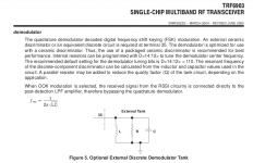
I have made the test, here are the test circuit, test configuration and a simulated ideal curve (the real curve might have an additional parallel resonance).
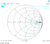
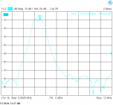
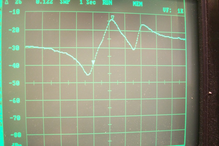
The frequency is swept from 10 to 12MHz:
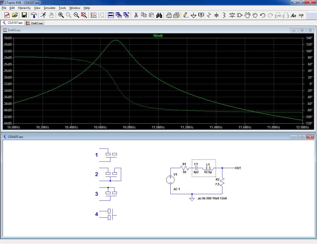
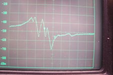
Configuration 1:

Too many things happen between 10.5 and 11MHz
Configuration 2:
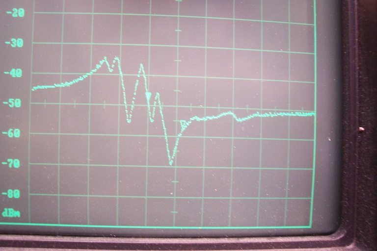
Broadly the same, even worse
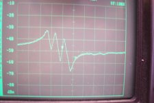
Configuration 3:
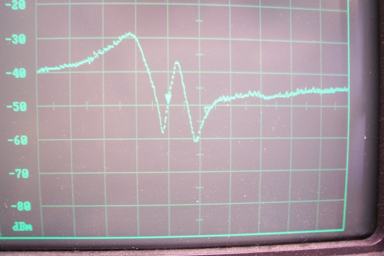
Much cleaner, but no usable resonance at 10.7MHz
Configuration 4:
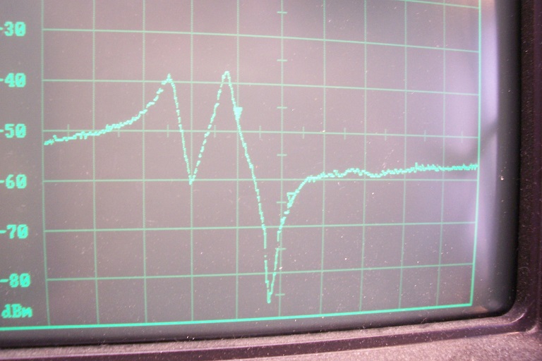
This one has a resonance at the right place (but also another one, almost as large)
The frequency is swept from 10 to 12MHz:
Configuration 1:
Too many things happen between 10.5 and 11MHz
Configuration 2:
Broadly the same, even worse
Configuration 3:
Much cleaner, but no usable resonance at 10.7MHz
Configuration 4:
This one has a resonance at the right place (but also another one, almost as large)
Attachments
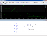


For my understanding, are you measuring the resonator's insertion gain in a 50 ohm system using a network analyser? Or, looking at the schematic, the insertion gain of the resonator and an 8.82 ohm resistor to ground in a 50 ohm system (as 8.82 ohm // 50 ohm ~= 7.5 ohm)?
Does the shape of the curves vary with the drive level? I have no experience measuring ceramic resonators, but I know you can easily drive crystals so hard that the shape of the response changes completely.
Assuming the plots indeed show insertion gain: pity that there is an extra bump in configurations 3 and 4. Without the extra bump, they would do precisely what you would expect from a two-pin ceramic resonator: first a peak due to series resonance, then at a slightly higher frequency a minimum due to parallel resonance (a.k.a. anti-resonance).
I guess that 10.7 MHz is supposed to be in between series resonance and anti-resonance of a 10.7 MHz ceramic discriminator. The filter of a quadrature detector is normally designed to have a phase shift of +90 degrees or -90 degrees at the centre frequency. Assuming the IC drives the discriminator from a small capacitor, the discriminator itself has to be somewhat inductive to get a phase shift of +90 degrees.
Configurations 1 and 3 are apparently the only configurations that behave inductively at 10.7 MHz, but 1 has series resonances that are too nearby to handle +/-75 kHz frequency deviation. If I were to try it, I'd go for configuration 3, possibly with a small trimmer in parallel to trim for minimum distortion, or a large trimmer in series if a small trimmer in parallel doesn't work.
More or less: I use a spectrum analyser as a scalar network analyser (thus no calibration, impedance normalisation or phase information).For my understanding, are you measuring the resonator's insertion gain in a 50 ohm system using a network analyser? Or, looking at the schematic, the insertion gain of the resonator and an 8.82 ohm resistor to ground in a 50 ohm system (as 8.82 ohm // 50 ohm ~= 7.5 ohm)?
The outlook of the curve is correct though
The stimulus is -10dBm, reducing it to -20dBm simply results in a downwards translation, thus no non-linear effectsDoes the shape of the curves vary with the drive level? I have no experience measuring ceramic resonators, but I know you can easily drive crystals so hard that the shape of the response changes completely.
I have also tried a shunt test configuration, but it shows practically nothing except for #4 again, which could almost be usable.
For provisional tests, it is probably the best option, but the quality will not match that of the real thing
I could imagine that in a shunt test, the 50 ohm // 50 ohm from the spectrum/network analyser practically shorts the resonator, so only very deep series resonances are visible. A T network consisting of a resistor in the kilo-ohm range (or a capacitor of 10 pF or so), a resonator to ground and another resistor in the kilo-ohm range (or a capacitor of 10 pF or so) will probably be more revealing.
I still suspect that configuration 3 will work best, as I expect the discriminator has to be in parallel resonance together with some driving capacitance from the IC. That is, if I were to design the IC, I would find a high-impedance resonator that I could drive from a small capacitance more convenient than a resonator that has an impedance minimum at the working frequency, but I don't really know how it was done, as none of the radio chips I worked on used a ceramic discriminator.
I still suspect that configuration 3 will work best, as I expect the discriminator has to be in parallel resonance together with some driving capacitance from the IC. That is, if I were to design the IC, I would find a high-impedance resonator that I could drive from a small capacitance more convenient than a resonator that has an impedance minimum at the working frequency, but I don't really know how it was done, as none of the radio chips I worked on used a ceramic discriminator.
I used a high-impedance probe, so it was actually 50ohm, but it doesnt fundamentally change matters.
It would be interesting to have access to the detailed characteristics of the resonator (motional parameters, etc.), but I could only find high-level, end-user data.
If I had one available, I could extract them, but I only have 3-pin types (and lots of 2-pin, but for other frequencies and applications thus probably not readily comparable).
Finding information on the internal workings of the chips is equally difficult
Murata publishes an application manual for their ceramic resonators. There is a little about how they work although it is not exhaustive. Link to the manual is below.
https://www.murata.com/-/media/webr...roducts/timingdevice/ceralock/p17e.ashx?la=en
https://www.murata.com/-/media/webr...roducts/timingdevice/ceralock/p17e.ashx?la=en
Yes, I found the same type of document for the Cerafil series, but it lacks real, fundamental data
If you really want, I can measure the S-parameters of Digikey 490-1229-1-nd
or 490-1230-1-nd on the ZVB8, but I don't think that leads to anything.
Esp. #3. The 2 ports of the filter are coupled internally and the phase between
them may go around several times over the passband, depending on the
number of internal resonators.
If at all, GND + one of the ports may work, with the other side terminated so
that almost nothing comes back. And then, the the frequency must be right.
Quite hopeless.
I have some 300 KHz and 460 KHz single resonators, the 300 KHz ones
have a piece of paper in the bag stating a series and par. resonance.
I must have measured that in a previous life, can't remember it.
But they seem to behave much like a crystal.
cheers, Gerhard
Last edited:
Indeed, a 2-port measurement isn't very meaningful, unless you have a simple way of extracting the equivalent s11 for all the possible 2-terminal configurations, but directly measuring the s11's would be simpler, and less prone to errors.If you really want, I can measure the S-parameters of Digikey 490-1229-1-nd
or 490-1230-1-nd on the ZVB8, but I don't think that leads to anything.
Esp. #3. The 2 ports of the filter are coupled internally and the phase between
them may go around several times over the passband, depending on the
number of internal resonators.
Yes, a low-grade crystal, having a much lower Q (which is necessary anyway for use in a wide FM demodulator)I have some 300 KHz and 460 KHz single resonators, the 300 KHz ones
have a piece of paper in the bag stating a series and par. resonance.
I must have measured that in a previous life, can't remember it.
But they seem to behave much like a crystal.
I'd be curious to see the parameters of these 2-pin resonators: it would allow simulation and comparisons.
Resonators for oscillators certainly have a much sharper characteristic.
I'm still struggling to get a full 2-port file. For my taste, the interface
of the ZVB is user hostile. The 2-port file is missing one column 😱
No idea why.
Since LTspice cannot easily handle s parameter files, a free alternative
would be QUCS or QUCS studio. A shame that the original author and
his group got splitted.
Easiest intro is via Gunthard Kraus' web site, which is also available in English.
Homepage von Gunthard Kraus
For S21, phase goes from +180° to -180° across the pass band and just outside
it still goes on if you mentally remove the wrapping at 180° . With 330 Ohm
terminations the insertion loss should be not that bad.
This is the 150 KHz version digikey 490-1230-1-nd SFECV10M7JA00-R0
Attachments
Last edited:
I am no great expert in Smith charts, but the region around M1 might be usable for demodulation, if it is wide enough.
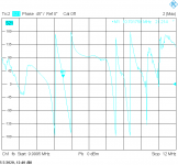
In the mean time, I have made shunt tests at higher impedance: 2K4 in parallel with a few pF:
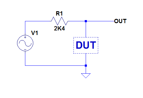
Center frequency is 10.7MHz, span 1MHz
This is configuration 3:
And configuration 4:

None look very usable.
In the mean time, I have made shunt tests at higher impedance: 2K4 in parallel with a few pF:
Center frequency is 10.7MHz, span 1MHz
This is configuration 3:
And configuration 4:
None look very usable.
Attachments
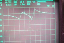
I don't get it. In post #8, there was a dip in the transfer around 10.76 MHz for configuration 3, which meant an impedance maximum. You now again get a dip at about the same frequency (slightly lower, 10.73 MHz), but as you have a parallel configuration, this time you need an impedance minimum to get a dip.
- Home
- Source & Line
- Analogue Source
- ceramic resonator 10.7MHz