As what he tweeter concerns, It usually breaks at the suspension ring where it vibrates most. Sometimes at the beginning of the coil (Very difficult to repair). I've had success with Q-tips embedded in acetone or paint thinner for finding the wire. When I was Young I even did it on headphones. The problem is usually removing the enamel from the wire. As You touch the wire with the iron, it wants to flee away.
It helps holding a screwdriver or similar tool on the other side of the iron and the wire between both to melt the enamel.
You need steady hands and patience, but it can be done.
It helps holding a screwdriver or similar tool on the other side of the iron and the wire between both to melt the enamel.
You need steady hands and patience, but it can be done.
Ok good you can solder 😎.Thanks Max. Very helpful.
I have changed caps previously and built kit-set amps - so hopefully I'm not too dangerous with the hot iron.
I'm just trying to learn more - rather than just become a "fitter" of new parts.
Caps use different dielectrics, in electros it's a thin film of insulating aluminium oxide (plus conductive liquid), in film caps its a layer of plastic, polyester or PolyPropylene are usual.
Different dielectrics have different loss properties and this translates to different sounds of capacitors with Polypropylene typically preferred.
Changing cap types ends up 'revoicing' loudspeakers, inserting a PP as tweeter series cap will usually clarify and extend the highs but may increase subjective SPL of the highs altering tonal balance of the loudspeaker.
This can be the improvement you want, sometimes you may need to decrease uF value of the tweeter series cap and perhaps alter value of tweeter attenuating resistor if fitted.
If you want to try some values replace C3 with 3.3uF PP and bridge C1 and C2 electros with 1.0uF PP or so.
This will 'liven up' the speakers and may give the sound you want but be prepared to tweak some values.
Hope this helps, let us know what you find.
Great information, thanks Max.
I have my order in, but capacitors finding their way to NZ from overseas sources are taking an age during this COVID-19 Lock-down.
I'm very much looking forward to trying some of these suggestions and reporting on the final outcomes.
Just one quick question: Am I right in saying that (regardless of capacitor type) reducing the capacitance value - from (say) 3.9uF to 3.3uF - of the tweeter series capacitor, will reduce the tweeter's lower frequency reach?
Have I got this right?
(Seeking answers, I have read and explored extensively on this specific topic and I can say that this definitive type of information is VERY hard to come by...)
You are correct, but remember that 3.9uF NP capacitors are manufactured, both as electrolytic and as polypropylene film. Just a matter of sourcing them in your part of the world. There's no problem in the UK, for example: 3 9 fd Monacor MKP Capacitor Or: 3 9 fd ECap70 Electrolytic CapacitorAm I right in saying that (regardless of capacitor type) reducing the capacitance value - from (say) 3.9uF to 3.3uF - of the tweeter series capacitor, will reduce the tweeter's lower frequency reach?
Thanks Galu.
If I am correct about a reduced tweeter capacitor reducing the lower frequency range of the tweeter, I'm a bit concerned that a 3.3uF capacitor value will create an undesirable sonic "hole" between tweeter and mid frequencies.
With that in mind, I will stick to the current 3.9uF capacitor - but this time in Polypropylene (PP) and see how the tweeter behaves.
The current aged 3.9uF EL capacitor actually measures 4.5uF, so an incoming PP capacitor at 3.9uF (or a little less as they often measure in reality...) should offset any additional SPL that the move from EL to PP causes. With a bit of luck, this small variation in cap value will not create the frequency hole I mentioned above.
Let's see.
Thanks again for all the great info. I will report back...
Last edited:
Another reason to change out old electrolytic caps is that as they age their voltage ratings go down as their capacitance goes up. Yours were rated at 35V which is quite low. Most older systems used at least 50V and current systems use 100V or higher. Better safe than sorry.
Another reason to change out old electrolytic caps is that as they age their voltage ratings go down as their capacitance goes up. Yours were rated at 35V which is quite low. Most older systems used at least 50V and current systems use 100V or higher. Better safe than sorry.
Thanks CM6. Good information here.
Am I right in saying that compared to the much larger MID and BASS series capacitors, the small TWEETER capacitor is the most at risk, relating to the (potential) long-term diminished voltage handling ability you mention?
I am also wondering if there is any kind of test for voltage handling, but assume that this type of test would destroy the capacitor in the process.
(Not what I'm looking for... LOL!)
Last edited:
The series tweeter cap does see the voltage so a cap that has become low voltage is not a good thing. If it's value has gone up, that pushes the crossover frequency lower as well which is also bad. If it blows and you're lucky, it blows open.
When I pick up some old speakers, if I have a chance to test them first I only play them at a really low level. I generally trace out the crossover to check that it wasn't altered then I always recap all the electrolytics and test and replace other stuff as necessary.
I've got the data somewhere about how some guys checked the caps for value and then slowly started increasing the voltage until they failed. So, yes, it is a destructive test.
So is it logical that the much smaller tweeter EL capacitor is at greater risk of diminished voltage handling over the decades - compared to the bigger MID/BASS EL caps?
Or is the size/capacitance of the cap largely irrelevant?
Or is the size/capacitance of the cap largely irrelevant?
So is it logical that the much smaller tweeter EL capacitor is at greater risk of diminished voltage handling over the decades - compared to the bigger MID/BASS EL caps?
Or is the size/capacitance of the cap largely irrelevant?
No, I don't think so. It is the one which has the probability of causing the most damage if it fails though.
I think the original quality of the cap and the conditions of use are the main factors. For instance if the cap was cheap and nasty to begin with and then it was mounted next to a power resistor that gets pretty hot its specifications will change much sooner.
As you may have noticed caps also have temperature ratings. The hotter they get even if below their maximum, the shorter their life.
Chris
No, there is no logic to a diminished voltage handling associated with a series capacitor feeding a tweeter. The problem that effects capacitors and in particular the electrolytic types is ESR and if this high then the capacitor can heat up which results in a loss of power to the speaker unit. I would not say that the size is irrelevant. Improved capacitors tend to use thicker insulating films and metal foil / metallised plates. This results in a larger physical size. Cost is the main reason non polarised electrolytic capacitors are used in crossover networks.
No, there is no logic to a diminished voltage handling associated with a series capacitor feeding a tweeter. The problem that effects capacitors and in particular the electrolytic types is ESR and if this high then the capacitor can heat up which results in a loss of power to the speaker unit. I would not say that the size is irrelevant. Improved capacitors tend to use thicker insulating films and metal foil / metallised plates. This results in a larger physical size. Cost is the main reason non polarised electrolytic capacitors are used in crossover networks.
If his capacitors were rated at 35V and through time have effectively lowered to around 25V, what exactly do you think will happen if his amp puts out 30V?
If the ESR has gone up which causes the cap to heat up that's not good either.
I thought the OP meant the capacitance value of the cap not the physical size.
In any case for equal values of capacitance and dielectric, the voltage rating determines the physical size. Some people feel that the higher the voltage rating the better it sounds. I just saw somebody opened up their Epos speaker and found it had a 630V cap feeding the tweeter.
Some people feel that the higher the voltage rating the better it sounds. I just saw somebody opened up their Epos speaker and found it had a 630V cap feeding the tweeter.
There's a whole new hornet's nest, right there... LOL!
Worth a try - I guess - if you already have the high voltage caps lying around doing nothing.
Repair and Upgrade Success!
I just wanted to round this thread off, with an outcome.
I decided that while I was under the hood replacing the blown tweeter - like for like - I would also try a few speaker upgrades... a la DANNY RICHIE of GR RESEARCH.
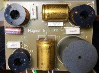
The three EL caps on the crossover measured superbly - out of circuit - but as a precautionary measure, I elected to replace the smaller (35-year old, West German) 3.9uF EL cap with two Polypropylene (MKP) caps.
One new cap was a high-quality 3.6uF 250VDC 5% that measured 3.556uF - quite a bit lower than the (over-value) 4.500uF cap it replaced - so I added a second new cap 0.222uF 1000VDC 5% that I have had lying around for years. The combined caps brought the capacitance up to 3.778uF which was about as close to the originally specified 3.9uF as I was going to get.
It was in my thinking that the slightly lower value of this new cap combo, would offset any additional volume the tweeter might gain through the move from EL to MKP.
Fortunately, I also have an identically measuring pair of the same two caps here, waiting for the other speaker.
While I was waiting around for new caps to arrive - still waiting, if fact - I also: -
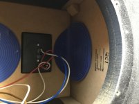
* Lined four of the speaker interior sides with 5mm acoustic mat;
* Installed three judiciously placed anti-back-wave "gel" pads;
* Dampened the Woofer Cradle with self-adhesive runs of acoustic dampener - taking care not to obstruct air-flow from the rear of the driver cone; and
* Rewired the Tweeter from old and thick copper multi-strand flex, to Audioquest Crystal 2 18AWG solid core, high-purity copper.
[Although I'd have liked to install decent binding posts, I've decided to save that job for another day - when I actually have my hands on a set...]
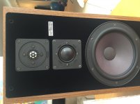
Last night was the moment of truth when my wife and I reinstalled the speakers into our system - both the repaired / upgraded speaker and the original - and took turns with the balance knob on our staunch little (15W) LEBEN CS300F tube amp, to compare sound, using a high quality MONO recording.
My wife did not know which speaker was which, but within the first few moments, the difference was patently obvious.
Aspects of the (texture) sounds in the music which were rendered in stark relief on the new upgrade, were totally MIA on the original speaker.
The original speaker - previously our favourite speaker with the LEBEN - now sounded murky, bloated and shut-in, by comparison.
This was right of the bat - with no time allowed for break-in.
Importantly, vocal images still remained strongly centered, indicating that the attenuation of the tweeters of the two speakers had remained constant.
We played quite a few albums - mostly STEREO thereafter - and the difference was extraordinary. Frankly, I was not expecting such an improvement - on our favourite speaker.
Needless to say, we are delighted with the outcome and will push forward and apply the identical upgrades to the original speaker.
Once we are able to get our hands on some quality binding posts, I fully expect that upgrade to provide yet another lift - as it has with previous speaker projects.
So a successful conclusion. Please find a few pics below.
Many thanks to all of the contributors below who have helped me make a success of this project - and have increased my knowledge bank on the way through. Appreciated.
-Tony & Rachel (SONDEKNZ)
I just wanted to round this thread off, with an outcome.
I decided that while I was under the hood replacing the blown tweeter - like for like - I would also try a few speaker upgrades... a la DANNY RICHIE of GR RESEARCH.
The three EL caps on the crossover measured superbly - out of circuit - but as a precautionary measure, I elected to replace the smaller (35-year old, West German) 3.9uF EL cap with two Polypropylene (MKP) caps.
One new cap was a high-quality 3.6uF 250VDC 5% that measured 3.556uF - quite a bit lower than the (over-value) 4.500uF cap it replaced - so I added a second new cap 0.222uF 1000VDC 5% that I have had lying around for years. The combined caps brought the capacitance up to 3.778uF which was about as close to the originally specified 3.9uF as I was going to get.
It was in my thinking that the slightly lower value of this new cap combo, would offset any additional volume the tweeter might gain through the move from EL to MKP.
Fortunately, I also have an identically measuring pair of the same two caps here, waiting for the other speaker.
While I was waiting around for new caps to arrive - still waiting, if fact - I also: -
* Lined four of the speaker interior sides with 5mm acoustic mat;
* Installed three judiciously placed anti-back-wave "gel" pads;
* Dampened the Woofer Cradle with self-adhesive runs of acoustic dampener - taking care not to obstruct air-flow from the rear of the driver cone; and
* Rewired the Tweeter from old and thick copper multi-strand flex, to Audioquest Crystal 2 18AWG solid core, high-purity copper.
[Although I'd have liked to install decent binding posts, I've decided to save that job for another day - when I actually have my hands on a set...]
Last night was the moment of truth when my wife and I reinstalled the speakers into our system - both the repaired / upgraded speaker and the original - and took turns with the balance knob on our staunch little (15W) LEBEN CS300F tube amp, to compare sound, using a high quality MONO recording.
My wife did not know which speaker was which, but within the first few moments, the difference was patently obvious.
Aspects of the (texture) sounds in the music which were rendered in stark relief on the new upgrade, were totally MIA on the original speaker.
The original speaker - previously our favourite speaker with the LEBEN - now sounded murky, bloated and shut-in, by comparison.
This was right of the bat - with no time allowed for break-in.
Importantly, vocal images still remained strongly centered, indicating that the attenuation of the tweeters of the two speakers had remained constant.
We played quite a few albums - mostly STEREO thereafter - and the difference was extraordinary. Frankly, I was not expecting such an improvement - on our favourite speaker.
Needless to say, we are delighted with the outcome and will push forward and apply the identical upgrades to the original speaker.
Once we are able to get our hands on some quality binding posts, I fully expect that upgrade to provide yet another lift - as it has with previous speaker projects.
So a successful conclusion. Please find a few pics below.
Many thanks to all of the contributors below who have helped me make a success of this project - and have increased my knowledge bank on the way through. Appreciated.
-Tony & Rachel (SONDEKNZ)
Attachments


Last edited:
- Home
- Loudspeakers
- Multi-Way
- TWEETER stopped working, but not open circuit...???