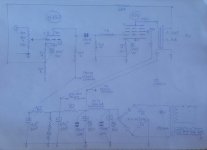
Annotation of diagrams … makes it simpler to talk about in forums, I think. Attached is an annotated copy of the original.
C1 looks like it should be 470 nF, to me. And OK if 'only' 250 V rated.
C2 has a 0.7 Hz –3 dB roll-off with R2. Seems pretty aggressive. Oh well.
C5 and C7 serve almost no useful purpose. Defense against … phantoms.
C9 at 22 µF is really quite small, given that it is providing filtering and reservoir for the critical first VAS stage.
R7, C3 are fine. –3 dB at 3.3 Hz.
There's no good reason not to have a defensive DC blocking resistor in front of VR1 (between top and input jack). Beautiful, cheap, great capacitors abound.
The combination of R3, R8 and the 17:1 ratio of T2 gives about ¹⁄₁₃₇ feedback network attenuation of overall gain. Which I've not calculated. What did you figure the open-loop gain to be?
Anyway, apart from those thoughts, the rest looks just fine.
I concur: could be useful for 2 to 3 output watts.
Might want to use a 220 V to 12.6 V toroidal power transformer for the output, if rated at about 75 VA to 100 VA nominally. Won't magnetically saturate. Same 17 to 1 ratio. Cheaper than a purpose-built transformer, especially for trying out the idea.
⋅-⋅-⋅ Just saying, ⋅-⋅-⋅
⋅-=≡ GoatGuy ✓ ≡=-⋅
Attachments
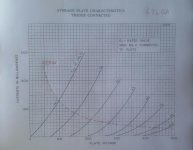
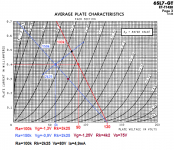
how would you draw the load line?If you don't need much power, the triode curves are workable for a few watts.
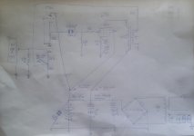
the only changes made were in the power supply (from T1S to C7) and C3 ...Annotation of diagrams … makes it simpler to talk about in forums, I think. Attached is an annotated copy of the original.
C1 looks like it should be 470 nF, to me. And OK if 'only' 250 V rated.
C2 has a 0.7 Hz –3 dB roll-off with R2. Seems pretty aggressive. Oh well.
C5 and C7 serve almost no useful purpose. Defense against … phantoms.
C9 at 22 µF is really quite small, given that it is providing filtering and reservoir for the critical first VAS stage.
R7, C3 are fine. –3 dB at 3.3 Hz.
There's no good reason not to have a defensive DC blocking resistor in front of VR1 (between top and input jack). Beautiful, cheap, great capacitors abound.
The combination of R3, R8 and the 17:1 ratio of T2 gives about ¹⁄₁₃₇ feedback network attenuation of overall gain. Which I've not calculated. What did you figure the open-loop gain to be?
Anyway, apart from those thoughts, the rest looks just fine.
I concur: could be useful for 2 to 3 output watts.
Might want to use a 220 V to 12.6 V toroidal power transformer for the output, if rated at about 75 VA to 100 VA nominally. Won't magnetically saturate. Same 17 to 1 ratio. Cheaper than a purpose-built transformer, especially for trying out the idea.
⋅-⋅-⋅ Just saying, ⋅-⋅-⋅
⋅-=≡ GoatGuy ✓ ≡=-⋅
Annotation of diagrams … makes it simpler to talk about in forums, I think. Attached is an annotated copy of the original.
C1 looks like it should be 470 nF, to me. And OK if 'only' 250 V rated.
C2 has a 0.7 Hz –3 dB roll-off with R2. Seems pretty aggressive. Oh well.
C5 and C7 serve almost no useful purpose. Defense against … phantoms.
C9 at 22 µF is really quite small, given that it is providing filtering and reservoir for the critical first VAS stage.
R7, C3 are fine. –3 dB at 3.3 Hz.
There's no good reason not to have a defensive DC blocking resistor in front of VR1 (between top and input jack). Beautiful, cheap, great capacitors abound.
The combination of R3, R8 and the 17:1 ratio of T2 gives about ¹⁄₁₃₇ feedback network attenuation of overall gain. Which I've not calculated. What did you figure the open-loop gain to be?
Anyway, apart from those thoughts, the rest looks just fine.
I concur: could be useful for 2 to 3 output watts.
Might want to use a 220 V to 12.6 V toroidal power transformer for the output, if rated at about 75 VA to 100 VA nominally. Won't magnetically saturate. Same 17 to 1 ratio. Cheaper than a purpose-built transformer, especially for trying out the idea.
⋅-⋅-⋅ Just saying, ⋅-⋅-⋅
⋅-=≡ GoatGuy ✓ ≡=-⋅
I love this forum!
I am finding a lot of kind and proactive people ... why don't you sketch it the way you would design it?
(originale design)
Attachments
RE: Post # 9.
Putting a capacitor across a gas regulator tube may not be a good idea.
Putting a capacitor across a gas regulator tube may not be a good idea.
Last edited:
RE: Post # 9.
Putting a capacitor across a gas regulator tube may not be a good idea.
I found It in different schematics...
There is something not right around the 6SL7.I love this forum!
I am finding a lot of kind and proactive people ... why don't you sketch it the way you would design it?
(originale design)
If you keep the Rk=2k2 change Ra from 100k to 150k
If you keep Ra=100k change Rk to 3k2.
Both cases give an Ia=0,4mA.
The values in the schematic give 0,5mA 70V and -Vg=1,1V not 0,4mA 90V and 0,9V.
But every combination functions, find out witch one sounds best.
Mona
Attachments
There is something not right around the 6SL7.
If you keep the Rk=2k2 change Ra from 100k to 150k
If you keep Ra=100k change Rk to 3k2.
Both cases give an Ia=0,4mA.
The values in the schematic give 0,5mA 70V and -Vg=1,1V not 0,4mA 90V and 0,9V.
But every combination functions, find out witch one sounds best.
Mona
If i increase It to 3k2, should not i decrease Ck accordingly?
No the Ck is big enough.If i increase It to 3k2, should not i decrease Ck accordingly?
Mona
No the Ck is big enough.
Mona
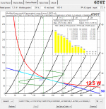
theoretically 25 uF should be enough to have a flat curve up to 20 hZ...
how would you draw the load line?
Here's a 5K loadline at 200V P-K and 60mA bias. You won't quite get two clean watts, but you could get two dirty ones.
Attachments

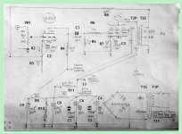
For those who want to build a well-sounding and inexpensive amplifier, I propose this project found on web which was replaced the tube power supply with a cheaper solid state one.
Tested, it sounds great.
Total component price: € 350
If it sounds OK, that is what matters. Don't put a scope on it, you may be disappointed!🙂
If it sounds OK, that is what matters. Don't put a scope on it, you may be disappointed!🙂
in fact I inserted this schematic to share it with those who don't have much money to spend and little technical knowledge like me and want to build a small amplifier with a very pleasant sound ... but as you can see, even in an amplifier designed by a professional there can be some imperfections as Mona pointed out.
Furthermore, the 6Y6 is a very underrated tube, perhaps due to the less usual voltage / current ratio or more simply because there are few projects around that enhance it.
- Home
- Amplifiers
- Tubes / Valves
- 6Y6 SE amplifier