Hi There, all well?
I have a question, I do want to make a shifted triangles with some digital components, however, I am not that educated with digital stuff but I think here will be guys who are.
It is about this part of a tut for class d. What do she mean and how this will be done, I do now about some things afcourse, like ripple counter, dflops.
The paper was not complete with drawns so I can not see how she did this, but it is interesting.
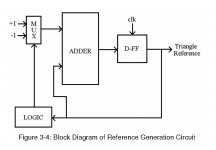
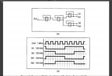
To ameliorate this issue, a four-phase triangular wave generator is used. This circuit includes a master integrator, a ripple counter, an encoder, and a 4-bit integrator. The master integrator is implemented to serve as an oscillator which generates a pulse signal, Q1. Since the master integrator circuit has identical behavior with the 4-bit integrators, the pulse signal Q1 can adapt to the characteristics of the 4-bit integrators. The operation of this master integrator can be described as follows: Assume the integrator is initially charging and its voltage begins to build up at its output. When 4V is
reached, the Q2 of the SR2 latch is triggered to logic high, MI1 is switched off, and the voltage of the integrator will remain still. When the external CLK
signal set SR1 to logic high, MI3 is switched on and the voltage of the integrator begins to decrease. When 1V is reached, the Q of both SR latches
becomes logic low, MI1 and MI2 begin to conduct and the voltage of the integrator begins to increase. These operations repeat indefinitely. Since the capacitor of the master integrator is only half the capacitance compared to the capacitors of the 4-bit integrator, the oscillation frequency of Q1 is doubled in comparison with the output of the 4-bit integrator, VC'. An encoder is used to generate the 4-bit phase control signal The CMFB circuits of the fully differential OP-AMPs will also help to stabilize the DC level of the output triangular waveforms.
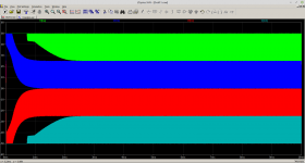
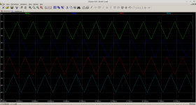
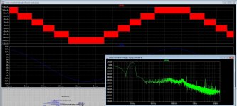
The system is multilevel class d, two sets of triangles 180 degree out of fase, with offset above and below zero, this digital one does prevent overlap.
Maybe discussion is interesting about clocked class d designs.
thanks and stay save.
I have a question, I do want to make a shifted triangles with some digital components, however, I am not that educated with digital stuff but I think here will be guys who are.
It is about this part of a tut for class d. What do she mean and how this will be done, I do now about some things afcourse, like ripple counter, dflops.
The paper was not complete with drawns so I can not see how she did this, but it is interesting.
To ameliorate this issue, a four-phase triangular wave generator is used. This circuit includes a master integrator, a ripple counter, an encoder, and a 4-bit integrator. The master integrator is implemented to serve as an oscillator which generates a pulse signal, Q1. Since the master integrator circuit has identical behavior with the 4-bit integrators, the pulse signal Q1 can adapt to the characteristics of the 4-bit integrators. The operation of this master integrator can be described as follows: Assume the integrator is initially charging and its voltage begins to build up at its output. When 4V is
reached, the Q2 of the SR2 latch is triggered to logic high, MI1 is switched off, and the voltage of the integrator will remain still. When the external CLK
signal set SR1 to logic high, MI3 is switched on and the voltage of the integrator begins to decrease. When 1V is reached, the Q of both SR latches
becomes logic low, MI1 and MI2 begin to conduct and the voltage of the integrator begins to increase. These operations repeat indefinitely. Since the capacitor of the master integrator is only half the capacitance compared to the capacitors of the 4-bit integrator, the oscillation frequency of Q1 is doubled in comparison with the output of the 4-bit integrator, VC'. An encoder is used to generate the 4-bit phase control signal The CMFB circuits of the fully differential OP-AMPs will also help to stabilize the DC level of the output triangular waveforms.
The system is multilevel class d, two sets of triangles 180 degree out of fase, with offset above and below zero, this digital one does prevent overlap.
Maybe discussion is interesting about clocked class d designs.
thanks and stay save.
Hi There, all well?
I have a question, I do want to make a shifted triangles with some digital components, however, I am not that educated with digital stuff but I think here will be guys who are.
It is about this part of a tut for class d. What do she mean and how this will be done, I do now about some things afcourse, like ripple counter, dflops.
The paper was not complete with drawns so I can not see how she did this, but it is interesting.
To ameliorate this issue, a four-phase triangular wave generator is used. This circuit includes a master integrator, a ripple counter, an encoder, and a 4-bit integrator. The master integrator is implemented to serve as an oscillator which generates a pulse signal, Q1. Since the master integrator circuit has identical behavior with the 4-bit integrators, the pulse signal Q1 can adapt to the characteristics of the 4-bit integrators. The operation of this master integrator can be described as follows: Assume the integrator is initially charging and its voltage begins to build up at its output. When 4V is
reached, the Q2 of the SR2 latch is triggered to logic high, MI1 is switched off, and the voltage of the integrator will remain still. When the external CLK
signal set SR1 to logic high, MI3 is switched on and the voltage of the integrator begins to decrease. When 1V is reached, the Q of both SR latches
becomes logic low, MI1 and MI2 begin to conduct and the voltage of the integrator begins to increase. These operations repeat indefinitely. Since the capacitor of the master integrator is only half the capacitance compared to the capacitors of the 4-bit integrator, the oscillation frequency of Q1 is doubled in comparison with the output of the 4-bit integrator, VC'. An encoder is used to generate the 4-bit phase control signal The CMFB circuits of the fully differential OP-AMPs will also help to stabilize the DC level of the output triangular waveforms.
The system is multilevel class d, two sets of triangles 180 degree out of fase, with offset above and below zero, this digital one does prevent overlap.
Maybe discussion is interesting about clocked class d designs.
thanks and stay save.
what you think is the benefit of such complicated circuit ?
do you think its audible v/s self oscillating ?
I think you should make focus on output mosfets / GaNs
Last edited:
A reference to the original paper would help.
Not exactly what you want but
...
Not exactly what you want but
...
Attachments
what you think is the benefit of such complicated circuit ?
do you think its audible v/s self oscillating ?
I think you should make focus on output mosfets / GaNs
I do multilevel, that can not be a self oscillating, except for three level max.
Digital is more precise with overlaps, what I need here to prevent crossover.
I like multilevel, it is better with efficienty and yes it is more complicated, however more manufacturers do use it, for it,s benefits, like low distortions, even open loop. I like do high quality, self oscollating are good some very good but want not stick with that alone, abroad mine horizon helps.
greetz.
Attachments
Last edited:
A reference to the original paper would help.
Not exactly what you want but
...
Yes thanks, I had this also done, but needs ripple counter encoder and 4 bit integrator, the 4 bit integrator is maybe the way you did with the opamps, I need to look at this further.
Thanks for the nice info.
greetz.
Last edited:
ohh I am to late
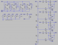
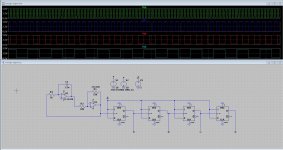
Here is what I think she mean, this is the master osc and the ripple counter, then we need a encoder, But what kind? then a 4 bit integrator masking the four signals fase shifted 180 degree. Did search on googe for 4 bit integrator, but none, do I need then a dac or such, mine digital knowledge is not that high.
regards
Attachments
It is about this part of a tut for class d.
You guys do realise you just did the OP's homework for him ... right?
You guys do realise you just did the OP's homework for him ... right?
Not quite, because I have done the version with 4 opamps in past already, but need a very stable offsets to prevent overlapping the triangles and afcourse the double sampling. The opamps has caps on input, digital is much more stable and precise I think, that is why these paper did mention that.
I had seen a pic also on internet of a digital triangle setup.
Attachments
Last edited:
http://oaji.net/articles/2017/1992-1525435871.pdf
OK... I get the desire to avoid overlap at zero crossing with the possible cross conduction. You mention you have done this in a similar way with op-amps before but it suffers from settling or set up time. That is always going to be the case even if you implement a digital solution. You just have to hold off on power switching until your digital or analogue circuit has settled. You can remove the input capacitors to the integrators if you buffer the offsets and then you can go one stage further and and servo the offsets. I have not looked closely at stability in the servo loops but perhaps one cute thing is that ripple gets cancelled.
...
Attachments

http://oaji.net/articles/2017/1992-1525435871.pdf
OK... I get the desire to avoid overlap at zero crossing with the possible cross conduction. You mention you have done this in a similar way with op-amps before but it suffers from settling or set up time. That is always going to be the case even if you implement a digital solution. You just have to hold off on power switching until your digital or analogue circuit has settled. You can remove the input capacitors to the integrators if you buffer the offsets and then you can go one stage further and and servo the offsets. I have not looked closely at stability in the servo loops but perhaps one cute thing is that ripple gets cancelled.
...
Thanks for the work you do for me I appreciate it.
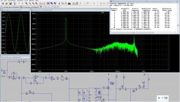
I had done this before and the question is not of the overlap can be prevented or not, it has to be prevented, but also the crossover and double sampling is a problem and distortion what happens, I had done a 8 level class d has in sim -100 dB beauty is, yes it is complicated, but I can use a very low switching frequency and can even with open loop get low distortion, but crossover or not depends of these overlaps, these need precise, even with 1 % resistors and a very stable supply, that is what I did read is that make it digitally, however the paper is not complete to see how it be done.
But talking about it, like here is very interesting afcourse, something away from normal class D is always interesting.
On pic is what I did a time ago, also with opamps following it, using dflops who have symetrical output voltages help get rid of capacitors and have a more steady offset.
Attachments
I've done similar myself given the logic is generally presented as being a simple means of producing quadrature, 90 degree, outputs. Unfortunately as you move to a higher number of phases, >4, the operation as what is effectively a ripple counter introduces timing delays. The ring counter method is synchronous so all edges change on the clock. It is also simply implemented using 74HC175 quad D type flip flops.
Looking at the paper,
http://oaji.net/articles/2017/1992-1525435871.pdf
The fact that the authors present a wordy description with no supporting diagram or circuit suggests that it might be more of a wish list than something that could be reliably implemented. Whilst they have the advantage of integration they still have to implement 5 capacitors, big on silicon and not necessarily such tight tolerance, so the result will probably suffer.
In amplitude terms you will always suffer from component tolerances but you also have to factor in timing delays. Rather than deal with them directly in as much as you can apply the servo method to the offset you could also adapt it to precisely adjust out cross conduction. Set up the servos to always drift into a result where cross-conduction is present and use a detection of that cross-conduction to continuously back them off.
With a bit of head scratching it should be possible in this case to generate all four triangles by using a single integrator and then just invert and level shift for the other outputs using basic amplifiers then servo them to the right place in terms of being on the limit of cross-conduction. That may/will be still limited by component tolerances and other contributors such as input voltage and bias offsets.
You might notice I have just done what the original authors have done and burbled a wish list.
I've done similar myself given the logic is generally presented as being a simple means of producing quadrature, 90 degree, outputs. Unfortunately as you move to a higher number of phases, >4, the operation as what is effectively a ripple counter introduces timing delays. The ring counter method is synchronous so all edges change on the clock. It is also simply implemented using 74HC175 quad D type flip flops.
Looking at the paper,
http://oaji.net/articles/2017/1992-1525435871.pdf
The fact that the authors present a wordy description with no supporting diagram or circuit suggests that it might be more of a wish list than something that could be reliably implemented. Whilst they have the advantage of integration they still have to implement 5 capacitors, big on silicon and not necessarily such tight tolerance, so the result will probably suffer.
In amplitude terms you will always suffer from component tolerances but you also have to factor in timing delays. Rather than deal with them directly in as much as you can apply the servo method to the offset you could also adapt it to precisely adjust out cross conduction. Set up the servos to always drift into a result where cross-conduction is present and use a detection of that cross-conduction to continuously back them off.
With a bit of head scratching it should be possible in this case to generate all four triangles by using a single integrator and then just invert and level shift for the other outputs using basic amplifiers then servo them to the right place in terms of being on the limit of cross-conduction. That may/will be still limited by component tolerances and other contributors such as input voltage and bias offsets.
You might notice I have just done what the original authors have done and burbled a wish list.
This was the paper from where I had this, as I did see I miss a lot of pages in it and as such I can not see what to do.
It is not that bad but here I have some older designs that I did try, for me, I go different because I do search something without feedback to see how high it can, for this I need low switching frequencies and multiply it by multilevel to prevent as much stwich errors as possible, the comparators are already more then fast enhough.
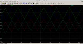
The bldc are two triangles 180 degree shift, then shifted in voltage for two of them to the negatief side, that make it more easy to do.
For the concerns of overlap, we talk about millivolts, here we need very precise resistors who make that ladder as you did, incl a high precision voltage source, I think that is why these people of the paper mention this digital stuff, but I have never seen a 4 bit integrator, is that a dac or so?.
Also the triangle need very lineair, but switching behavior is also present, so a distortion adjustment of the triangle can adjust the amps distortion.
here the 8 level tryout, with postfilter feedback, the feedback network is recalculated from a paper, and with that author I had mail exchange about it in multilevel amps, seen the faseshift in such network can ruin the multiplication factor and lose the supression of the lower switching frequency,s.
Schematic is a cascaded output, needs multy supply,s for a single one we need capacitor version.
regards
Attachments

http://oaji.net/articles/2017/1992-1525435871.pdf
OK... I get the desire to avoid overlap at zero crossing with the possible cross conduction. You mention you have done this in a similar way with op-amps before but it suffers from settling or set up time. That is always going to be the case even if you implement a digital solution. You just have to hold off on power switching until your digital or analogue circuit has settled. You can remove the input capacitors to the integrators if you buffer the offsets and then you can go one stage further and and servo the offsets. I have not looked closely at stability in the servo loops but perhaps one cute thing is that ripple gets cancelled.
...
I have look at article but not much found, so maybe the diea did not work well, however you have give some examples and this one has no caps on intput, however after some sim, these caps are not a problem anyway, the reference can be generated from a pricise voltage source so I go try later some of it.
Thans for the thinking, and stay save.
regards
- Home
- Amplifiers
- Class D
- making triangle digitally.