Hello all,
I am trying to make a diy single sided pcb for JLH1969 with all its 1969 version and the "1970 post script" modifications/ transistor substitutions as per following site. The Class-A Amplifier Site
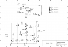
I have made a schematic, attached herewith. Could someone tell me if I am on the right track and if its a good idea to put PSU right on the amp PCB.
I need expert's / builder's inputs to optimize the design as much as possible.
I will post the design here, so diyer's have an option to build it themselves rather than Aliexpress / ebay kits.
regards
prasi
I am trying to make a diy single sided pcb for JLH1969 with all its 1969 version and the "1970 post script" modifications/ transistor substitutions as per following site. The Class-A Amplifier Site
I have made a schematic, attached herewith. Could someone tell me if I am on the right track and if its a good idea to put PSU right on the amp PCB.
I need expert's / builder's inputs to optimize the design as much as possible.
I will post the design here, so diyer's have an option to build it themselves rather than Aliexpress / ebay kits.
regards
prasi
Attachments

Last edited:

If you are bored you might like to build this for pennies. It sounds like a nice valve design. NE555 as Astable. Pin 5 is the modulator input. 40 uH is all I had, looks like a 1 watt resistor. 2200 uF is a bit large but OK. NE5532 suits well. The gain is required. 15 V is pushing my luck a little. The Astable ratio was a choice. I have a pair of JPW minims that go with an Armstrong 625. I never heard them so nice. Ideal little workshop amplifier and ideal for 1930's 78's. It's a better transistor radio. It's not very loud. I let it clip a bit. It's parts I had and not critical. I would love to try it with Klipsche Forte 2s. As said if you are bored and like me have these parts.
Hello all,
I am trying to make a diy single sided pcb for JLH1969 with all its 1969 version and the "1970 post script" modifications/ transistor substitutions as per following site. The Class-A Amplifier Site
I have made a schematic, attached herewith. Could someone tell me if I am on the right track and if its a good idea to put PSU right on the amp PCB.
I need expert's / builder's inputs to optimize the design as much as possible.
I will post the design here, so diyer's have an option to build it themselves rather than Aliexpress / ebay kits.
regards
prasi
prasi, have you seen this, what do you think?🙂 sublimed JLH1969 Not original anymore, but super interesting. I haven't built any JLH amps though.
Think about current flow: current flows in loops. There is no "common".Could someone tell me if I am on the right track and if its a good idea to put PSU right on the amp PCB.
I need expert's / builder's inputs to optimize the design as much as possible.
Don't mix power supply and signal currents.
Sit down and draw where the DC and AC currents flow. All of them. They you'll have good starting point.
And one wants to keep the small signal parts of the circuit on their own "clean" power supplies as far as practical. Not as big a problem with Class A as A/B (where we will have power rail sag/recharge)
Capacitive coupling is generally less of a problem, in my experience but again, keep the small signal stuff away from the large signal stuff.
Part of the joy of the JLH is its simplicity: there's really very little complexity to manage.
prasi, have you seen this, what do you think?🙂 sublimed JLH1969 Not original anymore, but super interesting. I haven't built any JLH amps though.
Hi tmuikku,
i would like to limit my work to original jlh1969 and original suggested psu and try to make it compatible with suggested transistors or modern equivalents. there are too many variants like hpa/ 2 pair, dual rail.
i am not designing any universal pcb, which would be too difficult if not impossible.
Think about current flow: current flows in loops. There is no "common".
Don't mix power supply and signal currents.
Sit down and draw where the DC and AC currents flow. All of them. They you'll have good starting point.
And one wants to keep the small signal parts of the circuit on their own "clean" power supplies as far as practical. Not as big a problem with Class A as A/B (where we will have power rail sag/recharge)
Capacitive coupling is generally less of a problem, in my experience but again, keep the small signal stuff away from the large signal stuff.
Part of the joy of the JLH is its simplicity: there's really very little complexity to manage.
For a moment there I thought I was reading Andrew.T , may God rest his soul in peace.
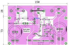
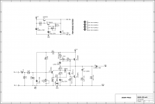
So here is a "dirty draft", beautification will come later once we are about to reach final stages. Followed the loops


big caps are 35mm dia, middle sizes are 20mm dia and smaller ones are 13mm dia. that should give plenty of options. I will also add pitch options in the final stages.
1. Input cap is big enough for folks? 37.5mm pitch 20 mm wide.
2. what will happen if we make C8 bigger say 2200uF or even 4700 uF
regards
prasi
Attachments
Last edited:
Hi Prasi, nice work on the JLH pcb's with cap multiplier onboard. If this is going to become a GB by you, then I will definitely take 2 boards for a stereo amp.
By the way have you looked at modern replacements for the hard to get and sometimes expensive 2N699, 2N1711 and the 2N 3906 - although the 3906 is still available I believe.
Cheers, Gary..
By the way have you looked at modern replacements for the hard to get and sometimes expensive 2N699, 2N1711 and the 2N 3906 - although the 3906 is still available I believe.
Cheers, Gary..
Hi Gary,
it will be diy design , so those who can etch their own pcbs can do so.
I can get a few pcbs manufactured if there is significant interest.
regarding transistors, MJ15003 and MJ21194 are available apart from the ubiquitous 2N3055.
2N1711 - although it seems to be available on farnell, manufacturer is unknown.
BD139-16 looks to be a good replacement. 2N3019 from microsemi also looks nice.
Plenty of 2N3906's on mouser.
However I leave the transistor substitutions to more experienced builders who have hands on experience with this design and who have tried different recipes.
regards
prasi
Thanks for the reply prasi. If no GB, I assume you will post the gerber files or equivalent so I can get pcb's done by one of the Chinese pcb manufacturers.
I can source some of the transistors and will get equivalents for others. Definitely will upgrade the 2N3055's.
I can source some of the transistors and will get equivalents for others. Definitely will upgrade the 2N3055's.
Dear Prasi,
In the schematic, It may be better to replace R2 with a resistance and a trimmer to adjust standing current as per the fig 1 of Dec 70 post script. Also, it may be better to provide place holders for the frequency tailoring components as per the fig 1. It may be better to follow the new schematic of JLLH of Dec 70.
--gannaji.
Thanks for the reply prasi. If no GB, I assume you will post the gerber files or equivalent so I can get pcb's done by one of the Chinese pcb manufacturers.
I can source some of the transistors and will get equivalents for others. Definitely will upgrade the 2N3055's.
Sure Gary, I will post all files, pdf/gerbers, sch, stuffing guide, BoM, etc.
I am hoping some of the builders / experts to chip in to make the design useful/ practical🙂.
regards
prasi
I would be very interested is this version of the JLH amp to drive my ESL57s.Really nice layout Prasi, would you consider doing the 2003 jlh with onboard multiplier.
Dear Prasi,
In the schematic, It may be better to replace R2 with a resistance and a trimmer to adjust standing current as per the fig 1 of Dec 70 post script. Also, it may be better to provide place holders for the frequency tailoring components as per the fig 1. It may be better to follow the new schematic of JLLH of Dec 70.
--gannaji.
Hello Gannaji,
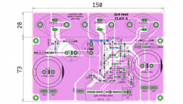
so, as an option i have included those components.
regards
prasi
To, Amplitude and Chilly,
I will take up 2003 layout with cap mx in near future, once this is finished.
I already have posted a 2003 design (without cap mx ofcourse) way back and also have few of pcbs lying with me.
regards
prasi
Attachments
Last edited:
Hello all,
I've started on my two boards
The outputs are left and right hand, the white wires
I've used Veropins for the items I will want to change
I'm making them as different boards so that I will be able to switch from one to the other to see which one I like best.
Cheers - J
I've started on my two boards
An externally hosted image should be here but it was not working when we last tested it.
The outputs are left and right hand, the white wires
I've used Veropins for the items I will want to change
I'm making them as different boards so that I will be able to switch from one to the other to see which one I like best.
Cheers - J
Hello Gannaji,
so, as an option i have included those components.
regards
prasi
Dear Prasi,
Beautiful layout !
That R13 is wire wound piece as per JLLH. Please check the foot print.
--gannaji
Last edited:
Hello Gannaji,
so, as an option i have included those components.
regards
prasi
To, Amplitude and Chilly,
I will take up 2003 layout with cap mx in near future, once this is finished.
I already have posted a 2003 design (without cap mx ofcourse) way back and also have few of pcbs lying with me.
regards
prasi
I think it could be a good idea to have the possibility to use a RC LP-filter on the input for EMI. I was shocked when I looked at the HF on the output from my JLH placed next to my TV.. I have now added a RC by cutting traces.
Some transistors options.
Hi, this is my first post. I recently started on electronics audio projects. I don't speak English very well, so forgive my mistakes.
I just finished two chanels on 1969 design, and I'm very happy with the results.
The transistors I've used are:
- shanken 2SC2837 for Q1 and Q2
- 2N1711 for Q3
- BC560 for Q4
Before i got 2N1711 had BC337 installed with similar results (No special measurement aquitement used)
Manel
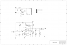
I think it could be a good idea to have the possibility to use a RC LP-filter on the input for EMI. I was shocked when I looked at the HF on the output from my JLH placed next to my TV.. I have now added a RC by cutting traces.
Done, as per jlh2003 schema.
Attachments

Last edited:
- Home
- Amplifiers
- Solid State
- JLH 10 Watt class A amplifier