I looked at your acoustic center file and I have to figure that a little point by point tutorial may come in handy:
Finding Acoustic Centers in XSim
1. All measurements must be with the same conditions so do not move the mic once it’s set up, do not move the speaker and do not change anything on the amp.
2. Set the mic up about 1 m away from the horizontal listening axis which 9 times out of ten is the tweeter axis.
For a 2-way, you need 3 measurements:
- tweeter only
- mid/woofer only
- tweeter and mid/woofer together
For a 3-way you need 5 measurements but a 6th will double check the work:
- tweeter only
- mid only
- woofer only
- tweeter and mid together
- tweeter and woofer together
- mid and woofer together
3. Stuff ports if vented.
Protect your tweeter: start your sweep at about 100Hz and keep the SPL’s low.
Gate at about 8msec which is accurate down to 125Hz.
Do not worry that baffle and room effect will be included.
4. For a 3-way:
- in XSim, create and wire up 3 drivers, then create 3 more that are unconnected.
- import the tweeter, mid and woofer only measurements into each of the connected drivers
- import the combination measurements into the unconnected drivers
- extract minimum phase from all measurements.
5. For the mid delay:
- connect the tweeter and mid so that they sum together (so disconnect the woofer from the circuit)
- display the System curve and the tweeter/mid curve (driver only) and now increase the mid delay until the 2 curves match as best as possible. That will be the difference in path lengths between the mic and the tweeter and the mic and the mid.
6. For the woofer delay:
- connect the tweeter and the woofer so they will sum together (so disconnect the mid from the circuit)
- display the System curve and the tweeter/woofer curve (driver only) and now increase the woofer delay until the 2 curves match as best as possible. That will be the difference in path lengths between the mic and the tweeter and the mic and the woofer.
7. To double check your values, connect the mid and the woofer so they will sum together (so disconnect the tweeter from the circuit)
- display the System curve and the mid/woofer curve (driver only). The 2 curves should now match with the delay values obtained in the last 2 steps.
8. Unlike PCD and VituixCAD (I think), XSim doesn’t allow you to input a driver's position on the baffle, ie. the x and y coordinates, nor is it actually inputting the actual driver acoustic center positions either. The difference in path lengths from the mic to each driver is not the same as the differences in their acoustic centers. The differences in the path lengths (driver delay in XSim) are part of the geometry that’s involved but so are the vertical positions on the baffle as well as the horizontal positions if the drivers aren’t vertically aligned. See the diagram with equations I posted back in post #42 on page 5.
This means that in XSim, if you wanted to see what the phase is like and therefore what the summed FR will look like at a position other than where the mic was originally, you will have to do the calculations yourself to get the new delays. In the other xo programs, these changes will be automatically calculated because the programs contain all the driver position variables that are involved in the geometry.
So if you want to do it in XSim, you need to go back to the equations for the simulated delay points and rework them to find the actual differences in the mid’s and the woofer’s acoustic centers. Not really that hard but just an extra step conceptually and mathematically. Got to say I think this is unfortunate – it’s one of the negatives in an otherwise very complete piece of software.
Acknowledgements to Jeff Bagby and his paper on the topic but written for PCD and not XSim - Box
Last edited:
This is a little different than the tutorial I followed, so that might explain why my measurements were off. Speaker acoustic center - How to find it | Audio Judgement They said measure each driver separately, then all three together. They also didn't say anything about stuffing the part. So basically we are treating this as two separate two way speakers. Makes sense.
Is this expected to be much different than the physical measurements we did earlier? Can this be simply drawn in CAD and measured there?
Is this expected to be much different than the physical measurements we did earlier? Can this be simply drawn in CAD and measured there?
It could if you actually knew exactly where the acoustic centers were for each driver. And there's the rub - they don't always correspond to some specific physical position on the driver. We can make our best guess - and we did for the purposes of simulations - but to get it absolutely right, it's best to measure.
Hopefully the measurement changes between the tweeter and mid. The phase doesn't seem to work out very well with the current measurements.
One thing I've been wondering about is taking near-field measurements with phase plugs. Do we position the mike on center of the phase plug or beside it closer to the cone? I see recommendations for both ways.
jwilhelm,
That's an excellent question. I haven't worked with a phase plug driver before so I don't know the answer. Maybe Douglas does. In Jeff's paper on measuring, he suggests that both are important but I think places a greater importance on measuring in the center of the driver. Placing it very close is about SPL differences between the cone vs baffle or room effects which can also be achieved by taking the measurements at higher SPL levels if the mic is a little further away from the cone. That's just a guess though. Maybe try each method and see if you get different results. Remember that the phase plug doesn't move so you should be able to put the mic as close to it as possible.
Now I've read the link you provided on finding relative acoustic centers and I have concerns. The problem is that he is trying to only use 2 driver responses to match the sum of 3 drivers. I can see how this could be accurate for the mid and the woofer in the LF's where the tweeter response has rolled off and is no longer contributing to the summed response but I can't quite see how it'll work for the tweeter and mid when the summed response is from all 3 drivers but he isn't using all 3 to make the match.
If you try both methods you can compare and I'd be interested in hearing which one you think is better.
I also looked at your individual driver measurements for finding the acoustic centers and interestingly this time the mid measurement looks a lot better. The SPL level looks right and the peaking problems are gone. Pic is below. So if you can get results closer to that again, we should be able to move to the next stage and work out a xo.
Attachments
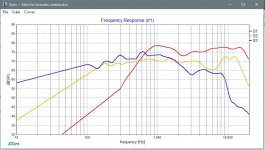
I did the acoustic center measurements with the microphone aimed at the tweeter, maybe the boost is happening only on axis with the mid-range? I hope to be able to take some more measurements this evening.
Ah, there it is - the piece of information we were missing. For farfield measurements, do the same thing you did for the acoustic center measurements - put the mic on the tweeter axis and then don't move it, don't move the speaker and don't change the amp setting. Then take each individual driver measurement.
For nearfield now move the mic to the mid and then the woofer. Then blend. I think that's going to fix things.
For nearfield now move the mic to the mid and then the woofer. Then blend. I think that's going to fix things.
I was under the impression the farfield measurements were supposed to be taken on axis with the driver under test?
Think of the mic as your ears. Do you move your head so that it is in front of each driver when you listen? Absolutely impossible. Instead your ears stay stationary at the same height as the tweeter, if that's the listening axis, or another point if you choose a different listening axis. Therefore, measure in the same fashion. Set the mic up on the listening axis and then take all the measurements from there.
That sounds much easier that moving for each measurement and trying to get the distance the same!
Exactly!! 
Mind you I have to say that if that is what you did, you actually did it exceedingly well. Woofer and tweeter were bang on with only the mid measurement getting screwed up.
Mind you I have to say that if that is what you did, you actually did it exceedingly well. Woofer and tweeter were bang on with only the mid measurement getting screwed up.
That's an excellent question. I haven't worked with a phase plug driver before so I don't know the answer. Maybe Douglas does.
This is why I keep the mic slightly above the baffle surface when measuring. The phase plug doesn't create it's own sound, rather it is supposed to even out the sound from the cone. By the time compression and rarification escape the cone-space they're pretty much well formed.
Also, when measuring close up vs 1 meter, I will take an individual driver's response and average the two together... (REW allows this in the ALL SPL window and produces a separate measurement for it) which seems to give a more accurate picture.
Mind you I have to say that if that is what you did, you actually did it exceedingly well. Woofer and tweeter were bang on with only the mid measurement getting screwed up.
If the goal is to get measurements that match the factory specs, why not just use the factory specs?
I thought the goal was to find out what effect the box has on the driver.
Or, in the service case... to get something to work with in the absence of factory specs.
What are you basing this on?which seems to give a more accurate picture.
This is why I keep the mic slightly above the baffle surface when measuring. The phase plug doesn't create it's own sound, rather it is supposed to even out the sound from the cone. By the time compression and rarification escape the cone-space they're pretty much well formed.
Also, when measuring close up vs 1 meter, I will take an individual driver's response and average the two together... (REW allows this in the ALL SPL window and produces a separate measurement for it) which seems to give a more accurate picture.
I think the idea of the two measurements is to use the nearfield for lower frequency because it doesn't include the room reflections, but use the farfield measurements for higher frequency so they include baffle step, ect. giving a more accurate overall measurement.
If the goal is to get measurements that match the factory specs, why not just use the factory specs?
Perhaps I misexplained.
I do not take matching specs as the goal. In this case for a beginner, I take the degree of correlation between the measurements and the simulations using the spec sheets to be a good sign about the accuracy of his measurements. Thus in the case of the mid, where the correlation was very small, I took it to mean that something was wrong. And it was.
I went through a phase like this. I found myself frustrated that I couldn't get good results and I fudged it. I was a newbie then, but even at the time I recognised it wasn't right.Also, when measuring close up vs 1 meter, I will take an individual driver's response and average the two together... (REW allows this in the ALL SPL window and produces a separate measurement for it) which seems to give a more accurate picture.

I think the idea of the two measurements is to use the nearfield for lower frequency because it doesn't include the room reflections, but use the farfield measurements for higher frequency so they include baffle step, ect. giving a more accurate overall measurement.
And where is the line between low and high?
That is going to depend on the room itself and it is very unlikely to correspond with any reasonable crossover point.
To be honest, I've never fussed over baffle step or it's implications for bass levels. I just average the near and far readings, design the crossover and if the bass is a bit low I will fix it with EQ, since, as I said, it almost never corresponds to any boundary we can get to in a passive crossover without massively complicating the design.
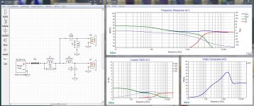
The thumbnail shows a typical baffle step circuit, tuned to about 200hz with 6db of attenuation.
The first thing to see is that you are dropping the output of your entire speaker rather pronouncedly for what amounts to a very small gain in Bass.
A 6db change is audible if you are listening to a single tone being modulated up and down 6db, but across frequency spectrum, a 6db rolloff is barely perceptable.
Note the current and power for the BS resistor (R1)... yep that's gonna be one beastie of a resistor. With musical decay taken into account I would want at least a 20 watter in there. And that coil is no slouch either, it would weigh a couple of pounds.
But why would we go through all that trouble when we can fix it with a slight twist of a tone control or a bit of boost on a low EQ band?
Maybe re-think this a bit... 😀
Attachments
Last edited:
- Home
- Loudspeakers
- Multi-Way
- Crossover Critique