
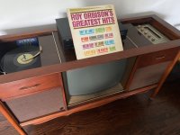
This is the unit...please excuse any dust bunnies.
OH!
That's one of those "home theater centers" with the 26 inch B/W TV.
An old friend had one - had remote-controlled TV. - heavy old monster too.
Uses the "600" series record changer.
We upgraded it - yanked out the TV chassis, installed a flatscreen that fit the width of the opening, with a DVD shelf below it.
I'll get back with info after I check the master book.
OH!
That's one of those "home theater centers" with the 26 inch B/W TV.
An old friend had one - had remote-controlled TV. - heavy old monster too.
Uses the "600" series record changer.
Exactly, the S600.
OH!
That's one of those "home theater centers" with the 26 inch B/W TV.
An old friend had one - had remote-controlled TV. - heavy old monster too.
The TV works, although we never turn it on - so I've never tried to fix the picture issues. It's fun every long once in a while to watch Twilight Zone or something on, though.
Attachments
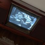
The TV works, although we never turn it on - so I've never tried to fix the picture issues. It's fun every long once in a while to watch Twilight Zone or something on, though.
The trouble is - with those old 1960 TVs, the flyback, coils, etc under the chassis are prone to self-destruction, and for obvious reasons, parts are no longer available.
The picture issues are a warning sign - take note.
The only solution is to tear it out and replace with something modern, after careful measuring and designing.
Last edited:
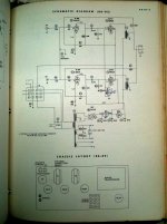
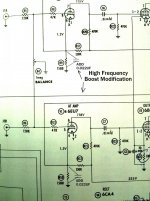
OK, so here's a schematic taken from my Maggie Service Bible........ (which also contains the S600 record changers, TV chassis, etc)
I added a simple "high frequency boost" modification that other 86 series amps have. (8601, 8603, etc)
You see, the design changes among the different chassis are related to differing cabinets, different speakers, etc.
I added a simple "high frequency boost" modification that other 86 series amps have. (8601, 8603, etc)
You see, the design changes among the different chassis are related to differing cabinets, different speakers, etc.
Attachments
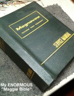
OK, so here's a schematic taken from my Maggie Service Bible........ (which also contains the S600 record changers, TV chassis, etc)
I added a simple "high frequency boost" modification that other 86 series amps have. (8601, 8603, etc)
You see, the design changes among the different chassis are related to differing cabinets, different speakers, etc.
I didn't know that - very interesting. As I say, though, using standalone speakers with the amp as-is it sounds fine so I'd like to try the other solutions suggested here to try to tame the mids first and then will save this for the next step if speaker adjusting doesn't work.
And thank you so much for this!
I have a later solid state model in a different style cabinet. The TV was gone when I got it, so I've been building a bar to go in that space.
That would be great to try provided John is comfortable working inside the chassis.I added a simple "high frequency boost" modification that other 86 series amps have.
Is there information in the manual regarding the impedances of the original drivers? There appears to be quite a variety of impedance among these units.
That would be great to try provided John is comfortable working inside the chassis.
Is there information in the manual regarding the impedances of the original drivers? There appears to be quite a variety of impedance among these units.
As I say I'll measure them directly once I can get into the cabinet later. We have two toddlers so bathtime is daddy's work-on-the-stereo time.
And I'm confident soldering inside the chassis, although I might need assistance via a photo of determining exactly where to put the inserted cap if we go that route just so I'm sure I have it in the right place. Would really like to try the L pad first, though.
I didn't know that - very interesting. As I say, though, using standalone speakers with the amp as-is it sounds fine so I'd like to try the other solutions suggested here to try to tame the mids first and then will save this for the next step if speaker adjusting doesn't work.
And thank you so much for this!
The thing is......
It might sound good with the standalone speakers, but you're going to use the console speakers - so you pattern the resulting sound accordingly.
A simple 8-10 ohm or so resistor in series with the midrange would tame them down.
Wire the tweeter with a capacitor directly to the woofer/amp output.
Trial and error is in the works.
You've only got 5 watts/channel with that 6BQ5 amp.
That would be great to try provided John is comfortable working inside the chassis.
Is there information in the manual regarding the impedances of the original drivers? There appears to be quite a variety of impedance among these units.
The amps are rated for 4 ohm speakers.
As I say I'll measure them directly once I can get into the cabinet later. We have two toddlers so bathtime is daddy's work-on-the-stereo time.
And I'm confident soldering inside the chassis, although I might need assistance via a photo of determining exactly where to put the inserted cap if we go that route just so I'm sure I have it in the right place. Would really like to try the L pad first, though.
The added capacitor (0.022uf/100v min rating) is merely jumped across the 1500 ohm cathode resistors - the tube pins are clearly marked in the schematic.
So here's how the drivers measured...
Original tweeter 3.5
Original mid 3.5
Original woofer 3.1
And the Vifa tweeter I replaced the original one with is 8 ohms. Sounds like my issue might be that I need a 4 ohm tweeter.
Original tweeter 3.5
Original mid 3.5
Original woofer 3.1
And the Vifa tweeter I replaced the original one with is 8 ohms. Sounds like my issue might be that I need a 4 ohm tweeter.
Last edited:
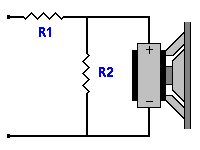
OK. Assuming the mid has an impedance around 4 ohm and we go for an attenuation of 3dB, here are some values to start experimenting with:
Series capacitor of 33uF followed by L pad resistors (see attachment) R1= 1.0 ohm and R2 = 10 ohm. Both resistors to be 10/15W ceramic (wire-wound) types.
Series capacitor of 33uF followed by L pad resistors (see attachment) R1= 1.0 ohm and R2 = 10 ohm. Both resistors to be 10/15W ceramic (wire-wound) types.
Attachments
That is not necessarily the case. The tweeter's sensitivity is more important in this application. And I suppose you can also experiment by going back to the original tweeter. As wiseoldtech says "Trial and error is in the works."Sounds like my issue might be that I need a 4 ohm tweeter.
The T35 will work just fine with a little bit of fine tuning, I'd probably go with either a 4 or 8 ohm Lpad, and to start with that 2.2uF capacitor you already have (most suitable for a 4 ohm lpad)
I salvaged the same series amplifier out of a different model console in Belgium after someone plugged it into 220V and blew up the power transformer. My first tube amplifier at the age of 17 or so. I was able to replace the power transformer and thought the amplifier sounded pretty good compared to the 5W per channel monolithic amp it replaced. Speakers were 4 ohm Lesa 6 inch full ranges in very small open back cabinets, sounded surprisingly good to me at the time.. 😀 (At it started me down the path that ultimately led to the complex tube based system I use today)
I salvaged the same series amplifier out of a different model console in Belgium after someone plugged it into 220V and blew up the power transformer. My first tube amplifier at the age of 17 or so. I was able to replace the power transformer and thought the amplifier sounded pretty good compared to the 5W per channel monolithic amp it replaced. Speakers were 4 ohm Lesa 6 inch full ranges in very small open back cabinets, sounded surprisingly good to me at the time.. 😀 (At it started me down the path that ultimately led to the complex tube based system I use today)
- Home
- Loudspeakers
- Multi-Way
- Scavenging Tannoy tweeter and crossover for vintage console