Hi!
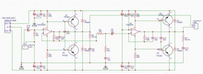
I am trying to build a mono amp based on bridged TDA2030 (2050) with output transistors TIP35/TIP36. I found a schematic that seems ok here https://320volt.com/wp-content/uploads/2009/03/200watt-anfi-devre-semasi.png and I copied it in EasyEDA to build a PCB. But I am not sure if I've done it correctly, particulary the transistors connections.
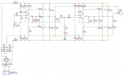
Here is my schematic:

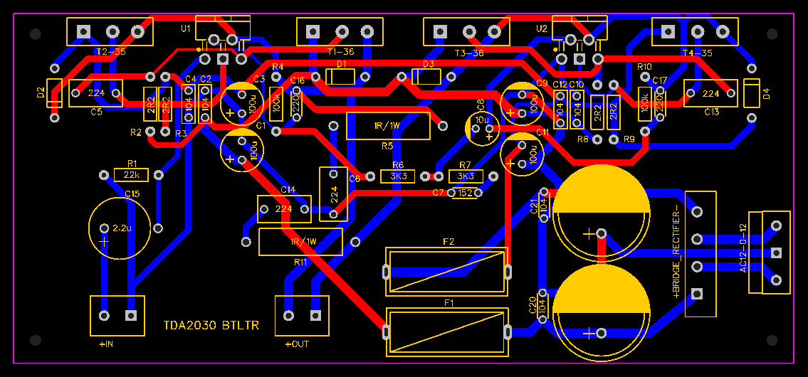
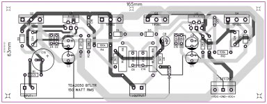
and here is an autorouted PCB I want to use as a reference:
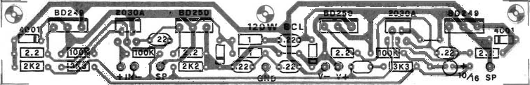
BUT with a similar schematic (I don't have the link, but is quite similar, without any input filterning and decoupling), the PCB looks entirely different, regarding the connections of the transistors (BDA249/TIP35C and BDA250/TIP36C):

I used schematics/footprints contributed by other users for TDA2030 and TIP35C/TIP36C and I din't change anything in pins/footprints.
Is my procedure that wrong?
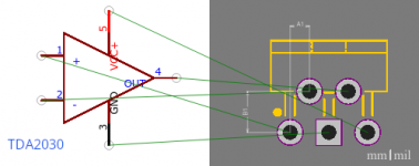
TDA2030 schematic and footprint:

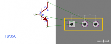
TIP35C schematic and footprint:

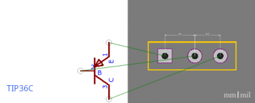
TIP36C schematic and footprint:

I am trying to build a mono amp based on bridged TDA2030 (2050) with output transistors TIP35/TIP36. I found a schematic that seems ok here https://320volt.com/wp-content/uploads/2009/03/200watt-anfi-devre-semasi.png and I copied it in EasyEDA to build a PCB. But I am not sure if I've done it correctly, particulary the transistors connections.
Here is my schematic:
and here is an autorouted PCB I want to use as a reference:
BUT with a similar schematic (I don't have the link, but is quite similar, without any input filterning and decoupling), the PCB looks entirely different, regarding the connections of the transistors (BDA249/TIP35C and BDA250/TIP36C):
I used schematics/footprints contributed by other users for TDA2030 and TIP35C/TIP36C and I din't change anything in pins/footprints.
Is my procedure that wrong?
TDA2030 schematic and footprint:
TIP35C schematic and footprint:
TIP36C schematic and footprint:
Attachments
I have the parts and I decided to give it a try, to gain experience and kill some (quarantine) time.
Hi milix
Asuslover is right, but i understand you that you want to try something.
i am not an expert and i did not try this schematic.
the chip and the transitors are very closed together, so with more power the distance and therefore the heat sink could be a problem, maybe try a layout left rigth separated?
the 22V supply do not give you 200Watt as posted in the link! 22V supply and a minimal voltage drop as super ideal is 2V each rail so you get 20Vpeak--> is 14,14Vrms and that give at 4R about 50Watt, in 2R about 100W ideal
read this:
IC Power Amps
just my 2 cent
chris
Last edited:
Hi chermann, thanks for the link!
Distortion in high frequencies is of no concern to me, as this amp (if it works) will be used as a subwoofer amp (8ohms) with an active lowpass filter before it. I will use two spare CPU heatsinks, with fans, I think they are sufficient
As for the 200W power, I totally agree with you, I didn't even take it seriously into account. The only component I will have to buy is the transformer, I am planning to buy a 14-0-14 toroidal transformer rated at 150VA (5.7A per rail)
Hi chermann, thanks for the link!
Distortion in high frequencies is of no concern to me, as this amp (if it works) will be used as a subwoofer amp (8ohms) with an active lowpass filter before it. I will use two spare CPU heatsinks, with fans, I think they are sufficient
As for the 200W power, I totally agree with you, I didn't even take it seriously into account. The only component I will have to buy is the transformer, I am planning to buy a 14-0-14 toroidal transformer rated at 150VA (5.7A per rail)
I would go for 8R sub and 160VA / 4,4A (34 euro)to a 18-0-18 (gives abotu 26V under load with 14000µF caps per rail.
14-0-14VAC give you about 21 V idle.
chris
I would go for 8R sub and 160VA / 4,4A (34 euro)to a 18-0-18 (gives about 26V under load with 14000µF caps per rail.
14-0-14VAC give you about 21 V idle.
chris
I didn't find an 18-0-18 160VA but I found a 17-0-17 160VA, priced at 32 euros, almost the same as the 14-0-14. So I'll go for it, thanks for the advice. About the 14000uF per rail, isn't it overkill? I know that more is better but 6800uF per rail isn't enough?
By the way, I found my mistake in the PCB, it was the pinouts of the transistors, I corrected them and now all tracks seem connected reasonably.
psu
please read this:
eBay mono LM1875 kit
and john audio tech video about power.
https://www.diyaudio.com/forums/chip-amps/341675-ebay-mono-lm1875-kit-21.html#post5943862
chris
I had this rule of thumb that for a quality amp, you should use a minimum of about 2000-3000uF per rail for each 100 Watt output. For a single rail amp, double that.
So if you use 6800 uF per rail you are well equipped.
Keep some Volt distance with the cap´s to the idle voltage, if you want to be on the safe side.
So with a transformer of 17V x 1.4 +5 = 24V you may use 25V caps, if they are of good quality. A little more with some unknown China brand.
If you have decided to use maybe 10.000uF, you often will have the same price for 2x 4.700uF. Two smaller capacitors in parallel will in most cases have a lower inner resistance. So instead of using one high end, low ESR cap, you may get the same result with two half the size.
Be careful not to use too small a rectifier, as these are stressed when switching the amp on and off. So for your 160VA 17V x2 Transformer, a 10A version would fit.
You can use one large rectifier for both ends of the transformer and ground (the middle contact) un-rectified or use two, one for each rail. Result is the same.
Last, put some small 0.47-4.7 uF film caps over the electrolytic´s.
They short fast transients disturbing the line. Their value is not very important.
Twist the + 0 - wires to the amp PCB.
The very nice Youtube video does not clearly mention that the capacitors have to match the amps output power.
If you build a sub woofer amp, you should in any case go for more capacity, if the transformer is on the small side and use a large rectifier.
PS there is no "too much capacity", but there is a point you will not have any improvement. Class A amps are a little different, but these are not the reality any more, even if often very nice.
Last edited:
Hi Turbowatch2, thanks for the advice!
I have four 6800uF/35V, unknown Chinese caps, I'll use 2 of them, one per rail.
I have a dozen of KBU251NWUS rectifiers (also Chinese), they suppose to be rated at 25A.
Also, in cases that there are 2 caps in parallel per rail, should I put one small cap for each electrolytic, in the bottom side of the pcb (so, two in total per rail) or just one at the end?
So with a transformer of 17V x 1.4 +5 = 24V you may use 25V caps, if they are of good quality. A little more with some unknown China brand.
I have four 6800uF/35V, unknown Chinese caps, I'll use 2 of them, one per rail.
Be careful not to use too small a rectifier, as these are stressed when switching the amp on and off. So for your 160VA 17V x2 Transformer, a 10A version would fit.
I have a dozen of KBU251NWUS rectifiers (also Chinese), they suppose to be rated at 25A.
Done that, with two 104 X7R ceramics. Should I use bigger (474) poly caps?Last, put some small 0.47-4.7 uF film caps over the electrolytic´s. They short fast transients disturbing the line. Their value is not very important.
Also, in cases that there are 2 caps in parallel per rail, should I put one small cap for each electrolytic, in the bottom side of the pcb (so, two in total per rail) or just one at the end?
Strange, thats the 2nd circuit in two days I have seen with bridge drawn wrong.
That's frustrating! I've seen dozens of such schematics and they had obvious (even to me) errors. The one I followed was the most promising to be correct, according to the schematic in Fig.20 published in the TDA2030 datasheet. Can you please point out the error? Thanks
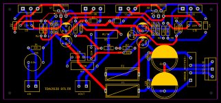
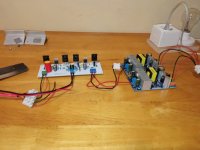
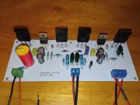
I made it and it actually works. The high-frequency response is not great, but the bass is there. This will be a subwoofer amp anyway.
Attachments
- Home
- Amplifiers
- Chip Amps
- TDA2030 BTL with output transistors