For no apparent reason, my brilliant 35-year old 3-way loudspeakers have just lost a tweeter.
Opening them up, it looks like they've never been touched - since the mid 1980s.
Upon inspection with my multi-meter, the tweeter circuit - and the main speaker inputs themselves - all still show electrical continuity.
The faulty speaker measures an unstable 6.6 Ohms (climbs to 6.8 Ohms) across the binding posts, whereas the good speaker reads a solid 6.1 Ohms.
The fuse, capacitors, resistors and inductors on the crossover all still show full electrical continuity.
There are no wires missing or broken.
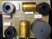
There are three different electrolytic capacitors on the crossover circuit.
01 x 68MFD / 35VAC
01 x 33MFD / 35VCD; and
01 x 3.9MFD / 35VCD (Presumably Tweeter Circuit...)
Could a faulty capacitor in the tweeter circuit - still providing full electrical continuity - be to blame for the dead tweeter?
[Puzzled...]
I'm waiting for an ESR METER to arrive from overseas (any day now...) - so I can test the capacitors - but until then, I was hoping someone might be able to shed some light here.
[Hoping I won't need to resort to trying the tweeter from the good speaker - in the faulty box...]
Opening them up, it looks like they've never been touched - since the mid 1980s.
Upon inspection with my multi-meter, the tweeter circuit - and the main speaker inputs themselves - all still show electrical continuity.
The faulty speaker measures an unstable 6.6 Ohms (climbs to 6.8 Ohms) across the binding posts, whereas the good speaker reads a solid 6.1 Ohms.
The fuse, capacitors, resistors and inductors on the crossover all still show full electrical continuity.
There are no wires missing or broken.
There are three different electrolytic capacitors on the crossover circuit.
01 x 68MFD / 35VAC
01 x 33MFD / 35VCD; and
01 x 3.9MFD / 35VCD (Presumably Tweeter Circuit...)
Could a faulty capacitor in the tweeter circuit - still providing full electrical continuity - be to blame for the dead tweeter?
[Puzzled...]
I'm waiting for an ESR METER to arrive from overseas (any day now...) - so I can test the capacitors - but until then, I was hoping someone might be able to shed some light here.
[Hoping I won't need to resort to trying the tweeter from the good speaker - in the faulty box...]
Attachments

Trying to measure a driver while its connected to a crossover is pointless.
You will need to disconnect and test the tweeter on its own.
Tweeters can be seized for a variety of reasons.
So even if it shows dc resistance on a multimeter still doesn't mean its working.
You will need to disconnect and test the tweeter on its own.
Tweeters can be seized for a variety of reasons.
So even if it shows dc resistance on a multimeter still doesn't mean its working.
Thanks for the tip...
At your suggestion, I have removed the Tweeter cables at the crossover board and the tweeter subsequently failed the electrical continuity test.
It seems I've got an open-circuit tweeter, after all. 🙁
Many thanks for the prompt assistance.
Appreciated.
At your suggestion, I have removed the Tweeter cables at the crossover board and the tweeter subsequently failed the electrical continuity test.
It seems I've got an open-circuit tweeter, after all. 🙁
Many thanks for the prompt assistance.
Appreciated.
If the tweeter did not fail at a high SPL, it is possible that only a litz wire has broken. This can be repaired.
Yes, there is break in the hair-like tweeter wire - and it did NOT fail under high SPLs. The wire break is so tiny, I can't actually see where it is broken.
I can't imagine a blob of (repair) solder on the hair-like wire will do anything good for the treble extension - but open to discussion on this. I'd love to be wrong about this and be able to repair the open circuit tweeter.
Fortunately, I had a spare tweeter on-hand, so the speaker is back up and running. However, now that the speaker is working again, I have opted to hold-off playing it, just in case the 35-year old electrolytic caps in the crossover are the reason the tweeter failed in the first place. They need testing.
Any day now, I will receive a new ESR METER in the post, so I can give them a check...
Well. A tiny amount of solder is still better than a broken wire for treble extension. Might as well give it a go. Just to have it as a backup
I agree with your caution. Tweeters need protection from the Bass power. You could well have a leaking crossover cap.
In my opinion, those 35 year old bipolar electrolytics don't warrant testing, but need replacing with modern electrolytic equivalents as a matter of course.
3-WAY Crossover Cap ESR Test Results!
This has been a very interesting little test.
Three electrolytic caps were measured - out of circuit, with one leg lifted.
(Interesting to note that the in-circuit test results were completely different. Lesson learned...)
OUT OF CIRCUIT MEASUREMENTS:
3.9uF/35VDC
ESR = 0.15
F = 4.50uF
VLOSS = 1.5%
If this is the tweeter Cap, is it possible that the slightly higher capacitance than specified forced the tweeter to operate lower than its ideal frequency, causing its demise? Or is .6uF over-value not worth losing sleep over?
33uF/35VDC
ESR = 0.03
F = 37.3uF
VLOSS = 0.9%
68uF/35VDC
ESR = 0.06
F = 73.6uF
VLOSS = 0.8%
These West German, shiny gold colored cans seem to measure well and look to be in pristine condition - so I'm VERY tempted to leave well enough alone.
But they are 35-years old.
I'm hoping someone with more experience can guide me here as to whether there is a chance that these caps are faulty, despite my measurements above.
Also as an aside, can anyone tell me for certain, exactly WHICH capacitor is the one in the tweeter circuit? I've studied the crossover and just cannot figure it out.
(Sorry. No schematics...)
Attachments
Last edited:
Those values don't look too bad. The initial tolerance was probably fairly wide.
The 3.9uF looks a bit battered.
Notice the resistor R3 is cooked, so the board has been hot
The 3.9uF looks a bit battered.
Notice the resistor R3 is cooked, so the board has been hot
Acceptable Levels of VLOSS???
@davidsrsb
Many thanks for your thoughts. Appreciated.
What I am not sure about is - what is an acceptable level of VLOSS on electrolytic caps in a speaker crossover circuit?
Is there any type of "rule of thumb" on this aspect?
(Upon close inspection, the discoloration on R3 is an old blob of glue. No other signs of heat damage...)
Those values don't look too bad. The initial tolerance was probably fairly wide.
The 3.9uF looks a bit battered.
Notice the resistor R3 is cooked, so the board has been hot
@davidsrsb
Many thanks for your thoughts. Appreciated.
What I am not sure about is - what is an acceptable level of VLOSS on electrolytic caps in a speaker crossover circuit?
Is there any type of "rule of thumb" on this aspect?
(Upon close inspection, the discoloration on R3 is an old blob of glue. No other signs of heat damage...)
In my opinion, those 35 year old bipolar electrolytics don't warrant testing, but need replacing with modern electrolytic equivalents as a matter of course.
+1 before you blow up another one.
Caps with large seal/bung diameter do not usually dry out especially in room temp application like speaker crossover and the caps do measure good so no need to change them and doing so will cause change in sound of the loudspeaker.+1 before you blow up another one.
The skill levels of OP are elementary, changing caps would be hazardous to health of these speakers.
The failed tweeter wire is most likely due to corrosion or fatigue and not the tweeter cap.
Max.
It is best to replace the higher value 33 and 68 mFd capacitors with new 100V DC non- polarised capacitor types and the 3.9 with a metallised polypropylene capacitor, which is the one in the tweeter circuit.
+1 before you blow up another one.
Thanks guys.
That may be where I am headed, but I'd also like to learn a bit more about the reasons for investing in replacements - before moving forward.
Here's the point: I have a handful of very good (and valuable) RUBYCON BLACK GATE VK SERIES electrolytic caps - and none of them measure any better than the caps 35-year old West German caps in my crossover.
Other brand-new RUBYCON electrolytic caps I have measure worse than the 25-year old caps in my crossover. Some have VLOSS as high as 1.6% from brand new!
I'd like to understand what my test results are saying. Otherwise testing is pointless and meaningless to me.
Can anyone else shed some light on these cap measurements for me?
Last edited:
Caps with large seal/bung diameter do not usually dry out especially in room temp application like speaker crossover and the caps do measure good so no need to change them and doing so will cause change in sound of the loudspeaker.
The skill levels of OP are elementary, changing caps would be hazardous to health of these speakers.
The failed tweeter wire is most likely due to corrosion or fatigue and not the tweeter cap.
Max.
%20Gecko%2F20100101%20Firefox%2F75.0&aac=&if=1&uid=1586919352&cid=2&v=458)
%20Gecko%2F20100101%20Firefox%2F75.0&aac=&if=1&uid=1586919352&cid=2&v=458)
Thanks Max. Very helpful.
I have changed caps previously and built kit-set amps - so hopefully I'm not too dangerous with the hot iron.
I'm just trying to learn more - rather than just become a "fitter" of new parts.
There is no definitive value of ESR for an electrolytic capacitor. It's magnitude depends on the method of construction (e.g. rough foil or smooth foil), electrolyte, capacitance value, working voltage, frequency and temperature.I'd like to understand what my test results are saying. Otherwise testing is pointless and meaningless to me.
Can anyone else shed some light on these cap measurements for me?
For minimum ESR in your tweeter circuit you can substiute a high voltage polypropylene capacitor for the current 3.9uF:35V electrolytic - as previously suggested by VaNarn.
Notice the resistor R3 is cooked, so the board has been hot
If you're right (I don't recognize so), the reason could be that this R3 might be connected in parallel wirh the tweeter and has consumed all the current due to the open voice coil. Anyway, no need to replace it if it still measures ok, as WW resistors can cope with overload for some time.
Best regards!
R3 Resistor measures fine...
Agreed. R3 measures 7.99 Ohms. Should be fine.
If you're right (I don't recognize so), the reason could be that this R3 might be connected in parallel wirh the tweeter and has consumed all the current due to the open voice coil. Anyway, no need to replace it if it still measures ok, as WW resistors can cope with overload for some time.
Best regards!
Agreed. R3 measures 7.99 Ohms. Should be fine.
- Home
- Loudspeakers
- Multi-Way
- TWEETER stopped working, but not open circuit...???