If there rises a question on specifics of crack initiation, propagation and testing of, you may ask. 🙂
George
One question George. When they are talking about the test and lubrication cycles am I right in assuming that, every 1600 (was 3000) cycles, so anything from once a year to every 3 years ish the whole engine comes out and is sent off to be stripped down, cleaned, inspected VERY thoroughly then carefully reassembled?
Again assumption from reading the slides, but I read from that that, after inspection the engine goes back into the same plane in the same location. If so this strip inspect and reassemble would have to be a fairly rapid turn around (1-2 weeks) as they don't like planes out of service too long.
Or do they just take the inlet fans off for inspection leaving the engine in place?
Just comparing with UK rail stock where they swap the body onto another engine unit to get it out the door then being maintaining the one left behind. But V12 turbo diesel electric powerplants are a very different beast.
I watched a show years ago where they discussed how turbine fan blades were made. IIRC, is a ‘single crystalline’ structure - it’s the only way they can be sure that material is uniform throughout the blade.
I believe Rolls Royce patented the single crystal fan blade process?😎
Re single crystal turbine blades
Re single crystal turbine blades
An easy to read, all you need to know
https://www.asme.org/wwwasmeorg/med...rks/brochure-single-crystal-turbine-blade.pdf
The devil is in the details (dentrite’s growth selective formation during slow solidification and control of solid-liquid metal phases)
It’s a story still in progress. Most patents on single crystal turbine blade manufacturing/alloy composition are assigned to USA corporations [United Technologies Corp. (P&W), GE)
Single metal crystal growth started in 1952 (USA 3060065). Manufacturing of single crystal metallic parts in 1962 (USA 3494709)
This one describes the famous ‘Rene 4’ 1st generation superalloy . Rich in background details and reference to the most important relevant patents thus far (1992). Recommended reading.
Nickel-based superalloys for producing single crystal articles having improved tolerance to low angle grain boundaries
1st stage of high pressure turbine vanes and blades are of very complicated structure due to extended hot air internal and surface cooling (lost wax casting and lased drilling)
YouTube
Today we are into 5th generation single crystal superalloys (say meta-material)
Multifunctional nanocellular single crystal nickel for turbine applications
And then comes Additive Manufacturing (metal powder 3D printing)
YouTube
https://netl.doe.gov/sites/default/files/event-proceedings/2015/utsr/Tuesday/Das.pdf
George
BillOne question George.
One cycle is from engine start to engine shut down. These engines go into mid sized planes which do easily 6 to 10 cycles/day. The fan blade relubrication then is every 5 to 9 months.
It’s a light maintenance action and it’s done with the engine on the pylon (‘in situ’ ). Start to finish it takes one to one and a half shift. Removal, cleaning, visual inspection, lubrication, reinstallation (not counting the engine test run).Usually it is scheduled to be performed during an ‘A Check’ in the hangar.
Depending on the running number of relubrication, more involved methods of inspection are required (dimentional, NDI), and the down time increases.
Blades are mass balanced and have to be numbered before removal. It is imperative to be reinstalled at the same fan disk slot. (In the engine records file, there is a record of blade S/N per disk slot position filled out during the last dynamic balancing test of the fan stage)
George
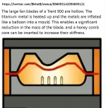
I think you mean a video that shows how they form titanium by compressed air. See attachment.I can't find the video where they show the bypass fan blades being inflated.
Good move if they have abandoned their previously mentioned titanium-skin over the honeycomb-core fan blades, an in-service nightmare (non repairable disbonding due to even moderate foreign object impact).These days composites and ceramics are all the rage but don't know if that's because only RR have the hollow Ti tech? Hopefully George will let us know.
As you imly, an all titanium hollow fan blade with internal trusses is an attractive design concept (and of minimum anticipated maintenance requirements). It has to compete in the field with the GE’s excellent CFRP fan blade design.
>Edit.Well I read RR too turns to a full CFRP fan blade design
Rolls-Royce starts manufacture of world’s largest fan blades – made of composite material – for next-generation UltraFan(R) demonstrator – Rolls-Royce
George
Attachments

Thank you George. The video I was looking for showed a man in full forge gear shoving a blade into the furnace. ISTR there is a very critical heating/cooling cycle for that phase.
The video I was looking for showed a man in full forge gear shoving a blade into the furnace. ISTR there is a very critical heating/cooling cycle for that phase.
Is this one Bill?
YouTube
against this GE’s CFRP fan blade
YouTube
No crucial manufacturing steps are to be shown in videos made public.
But as I linked to earlier, RR too turns to CFRP fan blades.
It’s not uncommon in the advanced composite materials field for a big team of experts to develop and advance a technology, then ‘lease’ the core of it to multiple big players. Same people behind innovative competitor’s products.
CFRP s are here to stay for manufacturing of ambient temperature operating blades (fan blades, propeller blades, helicopter main/tail rotor blades, wind el gen blades). 2D manufacturing, achieving impressive specs, still a fraction of static/dynamic specs compared to the target of 3D weaving of carbon fiber.
3D weaving requires really complex robotic custom-build, custom programmed weaving fixtures, not like the easy robots used now for to lay prepreg sheets.
As is the norm in aviation, component approval and certification is process and material specific. Once a component is certified, nothing - down to the most trivial detail - is allowed to change in the way of it’s making (*). So initial development costs are huge and only the big guys dare to take part in the game.
(*) any change requires recertification (that's very costly and slow going process)
George
Thanks for the appreciation guys 🙂
Bill I located two patents
Hollow component with internal damping - Rolls-Royce PLC
Method of manufacturing a component - Rolls-Royce PLC
These regarding the fan blade lubrication.
YouTube
YouTube
George
Hollow component with internal damping - Rolls-Royce PLC
Method of manufacturing a component - Rolls-Royce PLC
These regarding the fan blade lubrication.
YouTube
YouTube
George
Thanks
They are back into the commercial aviation game big time with the PW1X00 GTF engine family.
RR follows some years away (UltraFan engines).
Where you see huge fan diameters, there will be a reduction gearbox driving them (need for subsonic speed across the full length of fan blade)
Regional flights BAe 146 uses geared fan engines (Lycoming ALF 502) since 1983
George
Ah the 146. The plane BAe forgot to sell and only leased. I worked for them as the UK aerospace industry was falling apart 🙂
George,
Interesting information on those turbine blades and their various evolutions.
For a totally ignorant person in this field, could you be so nice to explain what the function of a gearbox is between the turbine blade and ????
Hans
Interesting information on those turbine blades and their various evolutions.
For a totally ignorant person in this field, could you be so nice to explain what the function of a gearbox is between the turbine blade and ????
Hans
On a non-geared turbofan engine, the fan is driven by a rotating shaft(*)what the function of a gearbox is between the turbine blade and ????
Hans
On a geared turbofan engine the driving shaft enters a reduction gearbox, the output of which drives the fan with a reduced angular velocity ω. The exercise aims to make fan blades function at subsonic tangential velocity (v= ω *r) along their full length, now that fan diameters becomes larger and larger. This old article explains it better than me (put fan blade in place of propeller blade).
Popular Science - Βιβλία Google
(*)Hans, I guess your question has to do with where does the driving shaft connects to at the other end, yes?
The other end is a turbine disk, the blades of which are hit by the exhaust gases of a constantly burning mixture of air and kerosene, thus turbine disk rotates and drives the shaft that rotates the fan disk.
The full story is more involved and more beautiful . The first paragraph (and it’s sub links) are enough if you don’t have the time to read the full article.🙂
Turbofan - Wikipedia
George
I worked for them as the UK aerospace industry was falling apart 🙂
Oh Bill
In my mind and in my heart, UK aerospace industry share the same place with the classic Norton Commando 750
George
George I agree. When I lived in Stevenage I was a few houses down from the Vincent factory. That was the peak of the british motorcycle industry, and as such doomed.
I did see some research engines a few years ago on engines that weren't quite turbfan and weren't quite turboprop but of course cannot find it now. Edit: Propfans. They appear to still be the technology of the future.
I did see some research engines a few years ago on engines that weren't quite turbfan and weren't quite turboprop but of course cannot find it now. Edit: Propfans. They appear to still be the technology of the future.
- Home
- Member Areas
- The Lounge
- The Black Hole......