This is a mistery box I bought a few months back. Came with the output tube broken, whick turned out to be an EL84. It was impossible to even try to recap it as is, but I messed up while drawing back the grid/feedback line of the end tube.
So far i have figured it to be a mixing amp with a single ended output.
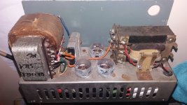
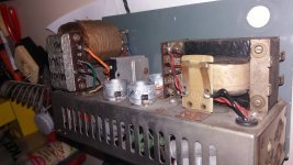
These are the best pics to show the machine itself, but already into disassemly. 1970-80s balkan DIY technology at its finest.
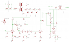
Here is my drawing too, any input is appreciated about any part of it and thanks already!
So far i have figured it to be a mixing amp with a single ended output.
These are the best pics to show the machine itself, but already into disassemly. 1970-80s balkan DIY technology at its finest.
Here is my drawing too, any input is appreciated about any part of it and thanks already!
Attachments
Are there specific questions you have?...any input is appreciated...
The mystery feedback network might have been a tone control - was there a label by the knob? What did it say? (The circuit will work fine with the entire feedback network removed - remove C8/R17/R19.)
R7 and R6 look too small, and will cause the 12AX7 to be biased very "warm", i.e. too much cathode current. I think 1.5k - 2.2k would be better choices here.
R11 looks too big - perhaps it was 4.7k and not 47k? The colours on the resistors are probably faded, and it may be hard to tell red from orange after so many years.
ECC83 1A/1B is the most sensitive part of the circuit. I would expect these would get their B+ from the *right* end of R11. ECC83 2A is less sensitive, and I would expect it would get its B+ from the *left* end of R11.
C3/C4 are much bigger than necessary. Even 22uF gets you a -3dB bass frequency down around 10 Hz. For a simple P.A. mixer, I think 10uF each for C3/C4 would be fine.
R21 is too big; it's most probably 1.2k, and not 12k. 12k is so big that ECC83 2A would be virtually cut off.
That's all that I spotted at a quick glance. If you have questions, do post them!
-Gnobuddy
Are there specific questions you have?
The main question is if the points marked ?B? should be connected, but you did not mention them, so I presume they are not.
...label by the knob?
No labels, just plain 3 knobs, a switch and a neon lamp on the front.
No info on the things life, I just think that this should have worked before. The connectors looked like they were used a lot, but they could have been already reused...
Im confident with the indicated values of the parts, there were no colorcoded resistors at all (I hate them 😀). But will check on them, I have them somewhere.
R7 and R6 look too small... biased very "warm"
Could this be because the tubes were worn out and the designer wanted to squeze a bit more time out of them? So any purpose or just a bad design choice?
R21 is too big; ECC83 2A would be virtually cut off.
Could this be because of the R6/R7 too small choice?
I cant decide that if all of these bad values are:
- bad design choices leading to more bad design choices (lack of knowledge)
- they had a purpose (warm preamp tubes, cold driver)
- the designer had to rely on what he could get his hands on (parts shortage)
Altough I bet on the first and last guesses combined.
R5 and R8 are very different in values, this makes me think that these are inputs for different instruments or an instrument and a mic. These determine the input impedance, so I guess 1M5 is most likely a guitar channel?
Thanks for your very valuable input again!
I will try to rebuild this piece in the original box, before the parts for the PP clone arrive.
I have some more questions regarding that project, about russian tubes; will gather my thoughts and post them there.
Definitely not. 🙂The main question is if the points marked ?B? should be connected,
Connecting those two would short-circuit the cathode of the EL84 to its own control grid. This would create zero bias for the EL84; it would then rapidly overheat and burn out!
A pity! 🙂...No labels...
Does that mean you measured all the resistance values? Unfortunately, old resistances - particularly carbon-composition resistors - change value dramatically as they age. After fifty or sixty years, the values you measured may have nothing to do with the original values at all.Im confident with the indicated values of the parts, there were no colorcoded resistors at all...
Also, somebody may have tried to repair or rebuild this circuit already in the past. If that happened, who knows what the original resistance values were!
In a guitar amp, there could have been a deliberate purpose (to create lots of harmonic distortion because the tubes were biased very "warm".)So any purpose or just a bad design choice?
But in a mixer? I don't think it was on purpose. I think those resistors used to be 1.5k or 2.2k in 1970, and have aged and drifted to the 1k value you measured recently. Or somebody put in the wrong value while trying to repair the device.
Of course I could be wrong...but I can't think of a good reason to bias those 12AX7 stages so extremely warm.
No, the two stages are AC coupled and so the values of R6/R7 have nothing to do with the quiescent (bias) point of ECC83 2A.Could this be because of the R6/R7 too small choice?
By the way, the circuit will definitely not work well if R21 is 12k. That value is quite definitely wrong!
The classic 2204 Marshall guitar preamp uses one centre-biased stage, one cold-biased stage, and one warm-biased stage, in that order. It was designed to distort a lot - to create "classic rock" sounds, which were new and exciting at the time. That was Marshall's target market, so designing to deliberately create lots and lots of distortion made sense.
But I cannot think of a good reason to do the same thing in an audio mixer. I guess it was a small P.A. system?
We can only guess. Another option - the original design was good, but the values you measured(?) recently are far, far from the original values because of component ageing. And yet another possibility: the original design was good, but somebody who knew very little tried to repair it, and made major mistakes.I cant decide that if all of these bad values are...
Hmm. That's an interesting thought.R5 and R8 are very different in values, this makes me think that these are inputs for different instruments or an instrument and a mic.
Looking at it again, R8 is so low that a moving-coil (dynamic) microphone is almost the only source I can think of that would match such a low impedance. But I don't think there is enough voltage gain for a microphone, by a wide margin.

We can make a rough estimate: at full output, there would be about 7 volts RMS, roughly, across an 8 ohm speaker (6 W RMS, in the right ballpark for a single-ended EL84). The output stage usually only has roughly unity voltage gain from control grid to loudspeaker terminals - the tube has gain, but the transformer attenuates voltage because of the step-down ratio, and usually these more or less cancel out, leaving roughly unity gain.
The preamp has a voltage gain of maybe 50x (34 dB), so you'd need about 150mV RMS at the "microphone" input, bare minimum. In practice you'd want a lot more than that, so that you don't have to turn the gain knobs all the way up to maximum.
And there is no way a dynamic microphone is going to put out 150 mV RMS with a normal human voice in front of it!
I bought my first Russian tubes recently, a few 6N2P. I built a circuit with them (an electric guitar preamp), but then my life suddenly became complicated, and I never finished the project. I need to go back and push it forward some more....about russian tubes...
-Gnobuddy
R7 and R6 look too small, and will cause the 12AX7 to be biased very "warm", i.e. too much cathode current. I think 1.5k - 2.2k would be better choices here.
Maybe 1K for R6 and R7 is correct. Philips datasheets for the ECC83 give Rk = 1K with Ra = 100K and Vb = 350 V. Notice R15 (2K7). The EL84 will draw about 45 mA at Va = about 250V so the voltage drop over R15 will be around 120V. So Vb for the first two triodes will be around 350V. Maybe the designer did this to achieve lower distortion (the hihger Vb, the lower the distortion for a given Vi of Vo).
The OPT in the schematic looks strange to me. If the EL84 is ultra-linear connected, the taps for B+ and screengrid should be reversed. But maybe the OPT has an anti-hum winding instead of an ultra-linear tap. Then the connections are drawn right, but in that case i would advise to decouple the screen of the EL84.
To Gnobuddy:
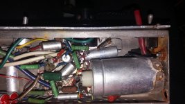
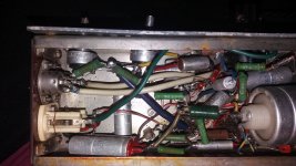
The resistors and capacitances are clearly marked with letters, the indicated values are what they should have been originally (they can be seen on some pics). I dont know if they are carbon (i have a databook on these components from 79, but they are older), i guess metal film, because they seem like a ceramic cylinder with a coating. I could scrape one out of curiosity, maybe later. But I have measured all the resistors upon removal, they were all in tolerance band.
To EL504:
The OPT could have been wired like a normal UL setup, have to look up on my hand scribblings.
I have a pocket book titled Radio technics pocket book (they had huuuge pockets back then, its nearly 1100 pages 😀) that has a spreadsheet for different tubes for preamp applications, that also says that the ECC83 could have 1k for Rk, with a supply of 350V and 100k RA or 300V and 47k. Will figure out what was the supply for the thing.
Am I right thinking that I can simply measure the ratio of my OPT with a variac and a volt meter; and I can make a guess on what impedance speaker can I use based on the optimal load of the EL84?
We should remember that this is an analogue circuit. Digital circuits either work perfectly, or not at all. But analogue circuits continue to work with imperfectly chosen resistors, they just exhibit degraded performance.Maybe 1K for R6 and R7 is correct. Philips datasheets for the ECC83 give Rk = 1K with Ra = 100K and Vb = 350 V.
There is a preamp stage in the Marshall 2203 and 2204 guitar amps that has an 820 ohm cathode resistor and a 100k anode resistor (and a half-12AX7 triode), running on 350 volts B+. It works, but clean headroom is (deliberately) very low: the tube is biased so warm that quite a small input signal will already force the output to begin to clip on negative half-cycles.
It's a similar story with 1k cathode resistors (along with 100k anode resistors and 350V B+.) Yes, the triode will still amplify. But it will be very warm-biased, and will have limited input headroom before the output starts to clip.
If the input signal was supposed to be very small (microphone, for example), this may not cause any problems. But the circuit as a whole doesn't have enough voltage gain for microphone inputs, and that suggests to me that it was designed for larger-than-mic-level input signals.
On the plus side, it is easy enough to build it, try it, and change resistors if you don't like the way it overloads with the 1k cathode resistors.
Maybe - but those 1k cathode resistors bias the triodes down to the lower left corner of the tube curves, the area where the tube is relatively non-linear, and distortion is higher as a result.Maybe the designer did this to achieve lower distortion (the higher Vb, the lower the distortion for a given Vi of Vo).
Good catch! Yes, as shown, there is positive feedback, which is very bad. The whole thing might take off and just oscillate at full power. Maybe R16 connects to the OPT centre-tap, not to the other end of the winding.If the EL84 is ultra-linear connected, the taps for B+ and screengrid should be reversed.
Looking at the area around the OPT, I would also expect a big electrolytic filter cap (several uF) from the right end of R15 to ground.
-Gnobuddy
Very interesting! I do not understand some of those values at all, for example the ridiculously too-big value of R21.The resistors and capacitances are clearly marked with letters, the indicated values are what they should have been originally (they can be seen on some pics).
Doesn't matter, since you went by printed resistance values, not by measurements. (Carbon composition resistors age poorly, and values drift a lot, so I thought you might have been mislead due to measuring 50 year old resistors.)I don't know if they are carbon...
Yes. Please be careful - winding ratio may be in excess of 25:1, so there will be high voltages involved on the primary side. Good thing you're an EE, so you know the dangers of high voltage electricity!Am I right thinking that I can simply measure the ratio of my OPT with a variac and a volt mete
That should get you in the ballpark. Keep in mind "optimal load" varies with B+ and screen grid voltage, so there isn't one single optimal value.I can make a guess on what impedance speaker can I use based on the optimal load of the EL84?
In North America there were a lot of 16 ohm speakers at one time, decades ago. I wonder if it was the same story in your part of Europe?
-Gnobuddy
winding ratio may be in excess of 25:1....
In North America there were a lot of 16 ohm speakers at one time, decades ago. I wonder if it was the same story in your part of Europe?
Seems like this had some exotic purpose or the OPT is faulty. I fed it 27,1V on the tube side from my soldering irons trafo. I got 6,5V on the secondary, that gives me 4,16:1 winding ratio, thats a 17,3:1 impedance ratio. Suggested impedance is 5k for the EL84, that gives about a 250 Ohm optimal speaker impedance.
The only thing that comes to my mind is 100V PA systems, where this could have been used, otherwise im totally puzzled 😕
Whats sure, that I can not rebuild it without an other OPT.
Suppose R21 = 12K is right. Without signal the third triode would be in (almost) cut-off condition. Only with high enough signal, it would start to amplify, but very distorted (it would operate more or less in class C).
This combined with the unusual winding ratio of the OPT makes me wonder if this could be part of some crude electronic switch or something like that. Maybe the output is for some relais. It will trip with enough inputsignal (audio?). The pots are for adjusting the treshold.
When measuring the OPT, did you try connecting the 27,1 V to the primary in more than one way (since there are 3 connections to the primary)?
How can you be sure that you have measured it across the full primary if you only tried one of the possible combinations?
I have measured DC resistances, to figure out the windings, the AC was applied accross the whole primary. Is there any new information in testing each winding separately?
I guess the big question is, what do you (hordri) actually want to build? Rebuild the original mystery device, with many unanswered questions as to its purpose? Or use the components in the mystery box as the basis for something new that you want to build?
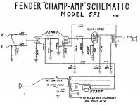
For example, you have more or less what is needed to build a Fender Champ (with an EL84 output stage rather than a 6V6, like the attached image). You would need a new output transformer, of course, and various other small parts.
Or you could build a more modern small guitar amp that came from the Champ family tree, but many generations more recent, such as the AX84 P1( AX84.com - The Cooperative Tube Guitar Amp Project ). It is Champ-like in many ways, but resistor and capacitor values and bias points and other components have been tweaked to make it more versatile, better sounding, and more suited to recent electric guitar music than Leo Fender's original Champ.
The AX84 P1 schematic is in the build document at the above link. If you want a peek, here it is: https://ax84.com/archive/ax84.com/static/p1/AX84_P1_101004.pdf
-Gnobuddy
Attachments
I see no point in restoring the original conditions and investigating the mistery. I have a rather big PP OPT with possibly damaged primary, I will try to trade it or sell it to get a suitable SE transformer. The mechanical parts will be enough to get some insight on the workings of the technology, try out some different curcuits as you suggested.
I was hoping for this to have the parts to start playing around with tube amps, sadly the OPT was not right.
I was hoping for this to have the parts to start playing around with tube amps, sadly the OPT was not right.
There is a source of very inexpensive transformers that can work in tube guitar amps: Cheap Output Transformers...sadly the OPT was not right.
In the USA, I can buy one of these audio line transformers for about $5 (USD), for example, this one: 70V 10W Speaker Line Matching Transformer
In Canada, a similar audio line transformer will probably cost me $25 CAD, and it is harder to find a supplier.
For use as cheap guitar amp OPTs, the USA "70 V audio line" standard is not as good as the Australian "100 V audio line" standard, because the 100V standard results in deeper step-down ratios, which are better suited for use in valve guitar amplifiers.
I don't know if this type of transformer (audio line transformer) exists in your country, but if they do, and if they are cheap enough there, it might be something to try.
These transformers were initially tried in push-pull DIY guitar amps, but a few people tried them in SE amps too, and were able to get them to work. Part of the secret is to use a too-big transformer, i.e. use a cheap 10-watt audio line transformer and build a 2-watt SE guitar amp with it. This way, the relatively oversized transformer has a better chance of coping with the DC current from the SE output stage.
There are some concerns regarding using these very cheap OPTs in valve guitar amps. One is that the inductance of the primary winding is much lower than "proper" expensive OPTs - this might limit deep bass response of the guitar amp. Fortunately, guitar signals don't go below 83 Hz in standard tuning, and most of the output from the guitar is above 160 Hz, so this is not as big a problem as you'd expect.
A second concern is the quality of the electrical insulation between primary and secondary of these "100V" or "70V" audio line transformers. They were not designed and tested and certified to withstand 3000 volts, like "proper" valve output transformers. So there is some fear of the insulation breaking down and dangerous voltages appearing on the speaker terminals. If you make sure the speaker is inside a box with the amplifier (i.e. a combo guitar amp, not separate head and cab), and remember never to touch any speaker cable ends while the amp is powered on, this may be an acceptable risk. (Dozens of Australian DIY guitar amp builders have used these audio line transformers, because "proper" valve output transformers are extremely expensive in Australia.)
-Gnobuddy
Thanks again for the valuable information, I will look out for these kind too. In the meantime I decided to order a proper OPT from china, it was still half the price of the trafo available here.
Now the waiting begins 🙂 Fortunately I have lots of other projects to dump some time into.
Now the waiting begins 🙂 Fortunately I have lots of other projects to dump some time into.
- Home
- Live Sound
- Instruments and Amps
- EL84 SE mixing mystery box