I do not understand the benefit of measuring a speaker buried in the ground[...] I don't really see how it would be usable.
Manufacturers use + publish IEC baffle results.
A buried baffle would be the same thing as an IEC baffle, but better.
Whether this amount of "better" is worth the effort is up for debate.
If I recall correctly, Earl Geddes said that one of his students did the buried thing, compared the plots to the same thing (unburied), and found that it made barely any difference.
Manufacturers use + publish IEC baffle results.
A buried baffle would be the same thing as an IEC baffle, but better.
An IEC baffle is close enough to 2Pi into bass territory that you can see the intrinsic response of a raw driver. Once you put a driver into a real cabinet that is going to exist some distance away from walls, I fail to see why anyone would care what it's 2pi radiation would be...unless you are designing in-wall speakers. In that case a buried cabinet would be ideal for measuring.
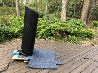
I put the mic on the ground, with the tip barely above the ground at some small angle. Then I find some way to tilt the speaker so that a line perpendicular from the speaker aims at the mic.
I was not paying close enough attention reading posts earlier, and thought you were advocating having the speaker on its side (which made no sense to me, but I was willing to try it).
It sounds like what you really meant is tilting the cabinet like in my picture. Unfortunately, I can't tilt my cabinet very far because the top and bottom sections are not actually bolted together. They just have really tacky Sorbothane between them. I also confirmed that tilting the cabinet only mitigates directivity and offers no other advantage, so I'm OK with stitching.
Attachments
I was not paying close enough attention reading posts earlier, and thought you were advocating having the speaker on its side (which made no sense to me, but I was willing to try it).
It sounds like what you really meant is tilting the cabinet like in my picture. Unfortunately, I can't tilt my cabinet very far because the top and bottom sections are not actually bolted together. They just have really tacky Sorbothane between them. I also confirmed that tilting the cabinet only mitigates directivity and offers no other advantage, so I'm OK with stitching.
Really cool you tried that....heck, i keep trying anything and everything trying to learn/get better measurements.
Looking at your picture, it appears the mic is well within 3X speaker height distance. ???
If/when so, I would expect stitching to be end up being fairly close to a single measurement. I mean, that's the 'stitch zone' ...before sound fully settles down / triangulates together acceptably.
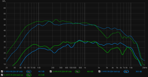
I did try measurements (indoors) with a speaker on its side (mic GP), and back (mic above, facing down). In both cases, the mid is in blue and the woofer in green. Dashed is side, solid facing up. This was just in the middle of the room, with lots of nearby objects, so I smoothed everything out to see the general trend.
What I am reading is that on its side I get a 2pi measurement; a worse version of burying in the ground and not useful. On its back, I get more baffle step than I expected. For the mid, I see the familiar diffraction peak at 750, a full 6dB of baffle step, and a small alignment bump at 100+Hz. For the woofer, I see 3-4dB baffle step and a larger alignment bump at 80Hz.
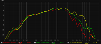
At this point, I believe I can take usable raw midrange measurements that are repeatable and verifiable in a completed design, but am still trying to do the same for the woofer. Before interpreting any more woofer measurements, my 2nd attachment has GP midrange measurements to set a baseline. Yeah, I know, x times baffle's greatest dimension, but my experience suggests width is critical and not height. Outdoors, I have found anything >4ft yields the same results for GP. 3ft is red, and 4 and 7ft in green and yellow.
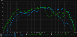
Now going back to that goofy speaker on its back measurements (3rd attachment). If I overlay outdoor GP measurements (dashed), it looks like I have been getting reliable woofer measurements all along. It may be that my only challenge has been verifying them in the completed design. Maybe I am going to have to break down and loft the speakers into the air in order to verify the woofer section.