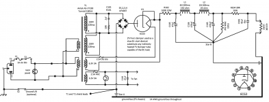
Attached is the schematic of a supply I have bread boarded here. Using a load of 4,910 ohms, (because that's what my big *** resistor is), the supply outputs 275 volts and draws about 54ma. With no load resistor the output is 328 volts, 0ma.
Next I wanted to see how much ripple it had. So I set my Fluke multimeter to AC and measured the output as AC. With the load resistor it reads an average of 70mv AC. With no load it reads an average of 2.5mv AC.
Are these acceptable ripple readings? Did I do this all right or am I all wrong herein how this is done? Is the ripple percentage a simple ratio of the DC voltage to the amount of AC ripple?
If its that simple then 70mv / 275000 =.00025% ripple loaded; and 2.5 / 328000 = .0000076% with no load.
Am I way off here in technique to determine how much ripple I have?
Attachments
Last edited:
You should get a basic scope with a x10 probe so you can see the waveforms directly.
Most of the ripple is being dropped across the 100R input resistor.
This will cause much more power dissipation in the 100R than you might otherwise expect
from the DC voltage drop alone. The two 470uF are much larger than would ordinarily be used.
Most of the ripple is being dropped across the 100R input resistor.
This will cause much more power dissipation in the 100R than you might otherwise expect
from the DC voltage drop alone. The two 470uF are much larger than would ordinarily be used.
Last edited:
You should get a basic scope with a x10 probe so you can see the waveforms directly.
Most of the ripple is being dropped across the 100R input resistor.
This will cause much more power dissipation in the 100R than you might otherwise expect
from the DC voltage drop alone. The two 470uF are much larger than would ordinarily be used.
Thanks. this is one of many iterations and the one I posted. I was planning on eliminating the 100R because the tube already has 25R. I had an iteration where the first 470 uf was 100 uf and didn't see much difference so I may go back to that. I like the way the voltage rises nice and slow over about 11 seconds which is what I wanted. But confused about what is considered acceptable ripple and how to measure it.
We can measure ripple as RMS (with multimeter) and as amplitude (with oscilloscope).
To get percent value we generally use amplitude of ripple voltage. Usually it have about-triangle form (so there isn't much need in oscilloscope). By knowing it's form we can calc amplitude from RMS value. The coefficient usually is about three.
So if ripple is 70 mV RMS then it has about 3x70 = 210 mV amplitude.
So ripplle is 0.21/275 = 0.08 %.
Last edited:
We can measure ripple as RMS (with multimeter) and as amplitude (with oscilloscope).
To get percent value we generally use amplitude of ripple voltage. Usually it have about-triangle form (so there isn't much need in oscilloscope). By knowing it's form we can calc amplitude from RMS value. The coefficient usually is about three.
So if ripple is 70 mV RMS then it has about 3x70 = 210 mV amplitude.
So ripplle is 0.21/275 = 0.08 %.
Ah thanks, I'm trying several part substitutes so I just need something simple like this to have a way to relate each iteration, if it's getting better or worse. Currently I'm getting 45 mV avg with the fluke in min/max/avg mode after some minor changes. I didn't put in the faster/softer diodes yet either or the snubber, will keep playing around. So feeling good about having some kind of relative measurement to use, thanks.
Attached is the schematic of a supply I have bread boarded here. Using a load of 4,910 ohms, (because that's what my big *** resistor is), the supply outputs 275 volts and draws about 54ma. With no load resistor the output is 328 volts, 0ma.
Next I wanted to see how much ripple it had. So I set my Fluke multimeter to AC and measured the output as AC. With the load resistor it reads an average of 70mv AC. With no load it reads an average of 2.5mv AC.
Are these acceptable ripple readings? Did I do this all right or am I all wrong herein how this is done? Is the ripple percentage a simple ratio of the DC voltage to the amount of AC ripple?
If its that simple then 70mv / 275000 =.00025% ripple loaded; and 2.5 / 328000 = .0000076% with no load.
Am I way off here in technique to determine how much ripple I have?
Your measurements are OK to a first approximation. Whether it is too high or not depends on your application.
What will it power? Does the amp you want to power start to hum with 70mV ripple or not? If it does, how much lower should it be to make it inaudible? It also makes a lot of difference how you construct it, whether it is SE or P-P, that kind of thing.
Increasing C106 will help, a film cap is not useful here. Better use a hefty electrolytic here and a film cap near the amp where the load is.
If you use a larger elcap, you may need to slightly reduce the series R to keep output the same.
Or use Ben Duncan's PSUDII for an online simulation to see which way you are going.
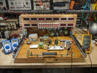
PS Like your breadboard, smart! The Heathkit does date you though ;-)
Jan
Last edited:
Your measurements are OK to a first approximation. Whether it is too high or not depends on your application.
What will it power? Does the amp you want to power start to hum with 70mV ripple or not? If it does, how much lower should it be to make it inaudible? It also makes a lot of difference how you construct it, whether it is SE or P-P, that kind of thing.
Increasing C106 will help, a film cap is not useful here. Better use a hefty electrolytic here and a film cap near the amp where the load is.
If you use a larger elcap, you may need to slightly reduce the series R to keep output the same.
Or use Ben Duncan's PSUDII for an online simulation to see which way you are going.
PS Like your breadboard, smart! The Heathkit does date you though ;-)
Jan
Thanks, it will be powering a computer desk amp with 2 6BX7 tubes and 2 6J6 tubes SE parallel dual triodes. I'm really not sure yet how much that will draw, I will determine that empirically at various playing volumes and sine frequencies on the breadboard after I get this power pack on a tray chassis off to the side to make room. The motor run cap was going to be at the amp, but I will play around with adding a larger el cap here and still keep the MRC cap on the top of the amp. It's a vanity cap anyway, when I wire brush it out on the bench grinder the oval caps look cool! It would be like the final decoupler one per channel, split at that point, not drawn here but that was the idea for the MRC caps.
The breadboard is magnetic, parts stay put even if I tilt it on end. So I don't have to disassemble a project when I want my bench back, just stand it on the floor. The meters have no common, all separate 9v batteries, safe. It's literally a breadboard chopping block with a steel plate, then I veneered the steel plate with real walnut self stick veneer PSA type. Then 3 coats of oil based floor finish Waterlox. I can use the base as ground plane. A big ground bus, because all circuits have grounds. The left and right rails have many different jacks terminated to barrier screws. The fused outlets at the back is for a feeds from bench supply. I made this last summer to increase my productivity.
Or use Ben Duncan's PSUDII for an online simulation to see which way you are going.
Ben Duncan <> Duncan Munro. The latter wrote the PSUD software.
Always take the bridge rectifier neg (or CT for a full-wave configuration) to the first filter cap (C103) negative terminal. If there is no load connected to C104, then connect C103 neg to C104 neg, and then C104 neg to C105 neg. C105 neg can separately go to the star B point for output stage. The aim is to separate the rectifier and filtering current loops to just their related parts - C105 onwards is then amplifier signal and power distribution related current loops, with the least interaction from the power supply current waveforms.
The connection you show is one of the most common reasons for noticeable hum in an amp.
Why have you fused the heater windings but not the HT ?
The connection you show is one of the most common reasons for noticeable hum in an amp.
Why have you fused the heater windings but not the HT ?
Always take the bridge rectifier neg (or CT for a full-wave configuration) to the first filter cap (C103) negative terminal. If there is no load connected to C104, then connect C103 neg to C104 neg, and then C104 neg to C105 neg. C105 neg can separately go to the star B point for output stage. The aim is to separate the rectifier and filtering current loops to just their related parts - C105 onwards is then amplifier signal and power distribution related current loops, with the least interaction from the power supply current waveforms.
The connection you show is one of the most common reasons for noticeable hum in an amp.
Why have you fused the heater windings but not the HT ?
Thanks, I'll redraw that, I may have a question later once I try to understand the ground flow you described, a picture will make that easier to ask in case I need to. I fused the damper heater only because it's hooked to the cathode here, heaters fail open, but I was thinking there may be a possible failure mode here with the cathode, wanted to protect the other winding. I suppose I could fuse the HT secondary too, to protect the tranny from a shorted diode? Diodes can fail short. The other 6.3 v winding is for the case fan since the damper will be inside the wooden case, other tubes are on top. The other tubes run off a separate dedicated 6.3 v torroid, AC filaments, not on this diagram, I had to add a separate filament tranny because it would have overloaded this tranny 3A available winding which I'll use for the fan.
Heaters typically have a very high and long in-rush current requirement - even a slow-blow fuse with a bit of margin above the heater continuous rating could blow.
A wide variety of faults could occur on the B+ rail. If a fault allows enough current to flow then collateral damage could extend beyond the power transformer HT windings, and also stress the chokes and any output transformer primary windings.
Your schematic should also show the 6CG3 heater and cathode as connecting by a separate link - your schematic indicates some heater current induced voltage may be added to the cathode voltage that goes to the first filter.
Are the snubber values used on the HT winding based on testing (as per Quasimodo style test setup), or are you just making a guess ?
You may want to ask Antek for clarity on the working voltage isolation design level of each of the secondary windings relative to other secondary windings, as there is no statement in their specs.
Not as simple as that. A dynamic load wil add ripple. With highish impedance output (39 ohms) the PS voltage will vary with load. A 50 ma change in load will cause a 2 volt change in PS output at DC. The last cap will reduce this as freq goes up so the larger the better. With all the components in that filter you would need to sim the circuit to get accurate numbers and they will change with the freq of the load current.
Heaters typically have a very high and long in-rush current requirement - even a slow-blow fuse with a bit of margin above the heater continuous rating could blow.
A wide variety of faults could occur on the B+ rail. If a fault allows enough current to flow then collateral damage could extend beyond the power transformer HT windings, and also stress the chokes and any output transformer primary windings.
Your schematic should also show the 6CG3 heater and cathode as connecting by a separate link - your schematic indicates some heater current induced voltage may be added to the cathode voltage that goes to the first filter.
Are the snubber values used on the HT winding based on testing (as per Quasimodo style test setup), or are you just making a guess ?
You may want to ask Antek for clarity on the working voltage isolation design level of each of the secondary windings relative to other secondary windings, as there is no statement in their specs.
Thanks
I will probably up the heater fuse to 4A that would be about double the 1.8A the heater draws when it stabilized. Antek tests the transformers beyond the amp ratings they publish.
The snubbers were a guess based on this long but great article on snubbers. The snubber is not bread boarded yet but its in the schematic. I should put that on and yes see if it makes any difference in measurement by trying out different values.
Taming the LM3886: Rectification and Snubbers – Neurochrome
Your schematic should also show the 6CG3 heater and cathode as connecting by a separate link
I'm not sure what you mean by this, is it just the way its drawn or should I change something here in the actual wiring? I elevated the heater this way researching how others are using dampers as an 11 second delay device.
Thanks for your time!
Came across this excellent paper, I think I need to read this over and do a little more work on PSUD2 to get the filter sections right. Also add the recommendations here, like tightening up the loop to bring the bridge negative directly to the first capacitor then to the bus, instead of through the bus then to the first cap. Back to the drawing board for a while.
https://www.dhtrob.com/overige/pdf/dhtrob_psu.pdf
https://www.dhtrob.com/overige/pdf/dhtrob_psu.pdf

Always take the bridge rectifier neg (or CT for a full-wave configuration) to the first filter cap (C103) negative terminal. If there is no load connected to C104, then connect C103 neg to C104 neg, and then C104 neg to C105 neg. C105 neg can separately go to the star B point for output stage. The aim is to separate the rectifier and filtering current loops to just their related parts - C105 onwards is then amplifier signal and power distribution related current loops, with the least interaction from the power supply current waveforms.
The connection you show is one of the most common reasons for noticeable hum in an amp.
Why have you fused the heater windings but not the HT ?
trobbins: I think I understood your ground flow here and redrew the diagram to keep the noisy part of the filter on a separate star, then brought the bleeder and final filter cap to the second star, which would start the audio ground. Also good news! I improved my original ripple by a factor of 8 going from an average of 70mV to a solid average of 9mV. Using the diagram you see. In the first test I was using IN4007's in the second I used UF4007's and I added the snubber RC. Also I brought the negative to the star instead of to the ground bus as in the original diagram. But the change that mattered the most is that I removed both the 100 and the 39 ohm resistors and upped the 2H 29 ohm choke (L2) to 6H 150 ohm just like L1 the only resistance now I guess is the 25 ohms of the 6CG3.
Here are my new measurements:
Load resistor was applied at point "LEFT" and is 4910 ohms
Total draw 55.6 mA
Output 282 VDC
Ripple 9 mV average after the load resistor comes to a constant temperature Fluke was left in averaging mode for a full minute.
I have a 100 Watt 15K rheostat on order so I can just dial in current draws at 10, 50, 100 and 150 mA to see how well the ripple does. The AudioCyclopedia describes another technique for measuring ripple with a RMS voltmeter similar to how I did this as well, and all the formulas to convert that to db. I plan on lashing that technique up too to see if they match.
Based on the approximate ad-hoc formula from VovK Z earlier here I'm just below 1% ripple. .027 / 282 = 0.9%. As for that being "acceptable" the AudioCyclopedia lists HiFi equipment as requiring ripple of 1% or better for a non-regulated supply. So I assume I'm on the right track here.
I also have my slow B+ rise which was the whole purpose here for me, full voltage occurs in the 11 seconds it takes the tube to warm up and ramps up nicely.
Your corrections on my grounding are much appreciated!
Last edited:
The requirement for snubbing becomes more dilute for valve HT windings due to their higher DCR and bulk capacitance, and any use of a valve diode.The snubbers were a guess based on this long but great article on snubbers. The snubber is not bread boarded yet but its in the schematic. I should put that on and yes see if it makes any difference in measurement by trying out different values.
Taming the LM3886: Rectification and Snubbers – Neurochrome
A normal valve rectifier diode has a relatively soft turn-off characteristic that markedly alleviates any transient generation - your 6CG3 has what seems to be a relatively high current rating (for what seems to be a low current amplifier requirement, but you haven't stated the load current clearly) so maybe not as soft a turn-off as say a 6X4. You may benefit from preparing a PSUD simulation, as that will clarify your transformer parameters, and load current, and peak diode currents.
There are also a few threads on the QuasiModo technique on diyaudio for deriving suitable snubber part values. I'd suggest the Quasimodo technique may suit you better if you really want to go down that path. Your link's technique indicates that you would be scoping a high voltage waveform, but also in a way that changes the grounding arrangement of the power supply (which may change your operating parasitics). The Quasimodo threads also have some discussion on waveform testing.
Your schematic does not show a Cx part for a typically deployed snubber.
> Output 282 VDC .... I have a 100 Watt 15K rheostat on order so I can just dial in current draws at 10, 50, 100 and 150 mA to see how well the ripple does.
Please run your video camera. The smoke may be exciting, and instructive.
(rounded) 300V at 150mA is 2k of resistance and 45 Watts of heat. 2k on a 15k rheostat is 13% rotation. Since only 13% of the winding is in circuit, a "100W" rheostat can only handle 13 Watts in that section of winding. OK, some heat will flow beyond the live winding into the dead part of the body, but not far. 20 Watts? Taking 45 Watts heat? (Actually it may not blow-up or burn. Turn the lights out it may glow dim red and STINK before quietly failing.)
10W resistors are cheap. 300V across 10k is 30mA and 9 Watts. Get a fist-full. You parallel for 30mA 60mA 90mA 120mA 150mA, lots of data. Since I think you really want lower current, get a second baggie of 100k 1W (Fender plate resistors); now you can load 3mA 6mA 9mA..15mA..30mA.
Betcha a bag of 10W and a bag of 1W is a lot cheaper than that monster pot.
Although if you ONLY want ripple data, one or two tests at reasonable current giving enough ripple to read well can be extrapolated to ANY current (as long as the ripple is not too obscene for an audio chassis; >30% ripple gets a bit nonlinear as we get into lumpwaves).
But (0.027/282) × 100% is 0.01%. ?View attachment 835035
Based on the approximate ad-hoc formula from VovK Z earlier here I'm just below 1% ripple. .027 / 282 = 0.9%.
- Home
- Amplifiers
- Power Supplies
- Is my ripple acceptable here?