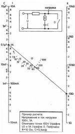
Here is a good diagram how to estimate RC snubber for low-frequency circuits. You should trace a line through two points: current and voltage. That line will show you R and C.
Attachments
Last edited:
Here is a good diagram how to estimate RC snubber for low-frequency circuits. You should trace a line through two points: current and voltage. That line will show you R and C.
Thanks! And also thanks on my math.
There is also one other change I'm going to try later today to see if it lowers the ripple even further. Currently the heater is tied to the cathode, this was done because many other rectifiers would fail on max heater heater negative relative to cathode voltage of 100v. But I looked up this tube and the heater neg to cathode rating is 900v with a peak of 5000v.
By hooking the heater to the cathode am I not injecting some AC ripple directly into my already rectified positive? Not sure. But I think with this tube I can safely disconnect the filament from the cathode. I'll try that and report back later if the average 9 mV of ripple goes down.
By hooking the heater to the cathode am I not injecting some AC ripple directly into my already rectified positive? Not sure. But I think with this tube I can safely disconnect the filament from the cathode. I'll try that and report back later if the average 9 mV of ripple goes down.
> Output 282 VDC .... I have a 100 Watt 15K rheostat on order so I can just dial in current draws at 10, 50, 100 and 150 mA to see how well the ripple does.
Please run your video camera. The smoke may be exciting, and instructive.
(rounded) 300V at 150mA is 2k of resistance and 45 Watts of heat. 2k on a 15k rheostat is 13% rotation. Since only 13% of the winding is in circuit, a "100W" rheostat can only handle 13 Watts in that section of winding. OK, some heat will flow beyond the live winding into the dead part of the body, but not far. 20 Watts? Taking 45 Watts heat? (Actually it may not blow-up or burn. Turn the lights out it may glow dim red and STINK before quietly failing.)
10W resistors are cheap. 300V across 10k is 30mA and 9 Watts. Get a fist-full. You parallel for 30mA 60mA 90mA 120mA 150mA, lots of data. Since I think you really want lower current, get a second baggie of 100k 1W (Fender plate resistors); now you can load 3mA 6mA 9mA..15mA..30mA.
Betcha a bag of 10W and a bag of 1W is a lot cheaper than that monster pot.
Although if you ONLY want ripple data, one or two tests at reasonable current giving enough ripple to read well can be extrapolated to ANY current (as long as the ripple is not too obscene for an audio chassis; >30% ripple gets a bit nonlinear as we get into lumpwaves).
Oh man thank you for saving me from that mistake PRR, you had my "6:00" there for sure. I thought a 100W rheostat was 100W all the way around! I have a bunch of those Chinese aluminum 100w resistors I'll have to see how I can trim them together to get the loads I want. Currently I'm using an old 1920's 5000 ohm 100w Ohmite 7 inch long brown devil. I have a bunch of 10 watters too, maybe I'll make a load box with a bunch of banana jacks and resistors where I could jumper whatever I want together at a higher wattage than my resistor substitution box.
Thanks again, seriously
Thanks again, seriously
Last edited:
The requirement for snubbing becomes more dilute for valve HT windings due to their higher DCR and bulk capacitance, and any use of a valve diode.
.
Your schematic does not show a Cx part for a typically deployed snubber.
Thanks again, ordering some class X capacitors in various values today. I only had a Mallory 630v to breadboard this for now.
There is also one other change I'm going to try later today to see if it lowers the ripple even further. Currently the heater is tied to the cathode, this was done because many other rectifiers would fail on max heater heater negative relative to cathode voltage of 100v. But I looked up this tube and the heater neg to cathode rating is 900v with a peak of 5000v.
By hooking the heater to the cathode am I not injecting some AC ripple directly into my already rectified positive? Not sure. But I think with this tube I can safely disconnect the filament from the cathode. I'll try that and report back later if the average 9 mV of ripple goes down.
OK 5 minutes to do this simple test, but the results were not what I expected... I disconnected the filament from the cathode thinking less ripple. But the result seemed to be more "clumping" of the swings, with a greater difference between min and max on both low and high mA bursts. With the disconnected filament the average went to 10 mV but with the filament elevated to cathode the average is 9 mV but with less differences between min and max occurring. In other words the "bursts" are more consistent with the filament elevated and the min/max tighter. When the filament floats the bursts are less consistent, I might see 10 seconds of 4 mV which is lower than the elevated min but occasionally I'll see a burst of 70 mV which is way above anything seen when filament elevated, so the min/max is not as "tight". But the average mV is not much different for both 9mV elevated vs 10-11 mV floating, (averaged over 1 minute after the big *** resistor reaches a stable hotness).
I think I like the behavior of having the filament elevated better, so thats how I'll leave it. I see less "clumping" and "bursting" and the average is still 1 mV better. Not the results I expected but that's what makes electronics fun!
The 6CG3 diode uses an indirectly heated cathode - its heater supply does not add or subtract ripple voltage from the cathode connection to the filtering stages - you may have assumed that it did by the way you originally drew your schematic.
Although the 6CG3 has a high cathode to heater voltage rating for a heater that is connected to 0V, there will be some leakage current through that interface. If your 6CG3 has a poor heater-cathode resistance, then depending on where you have connected the heater supply to your 0V, you may have ripple getting in to your power circuit - the 6CG3 heater should have a link to the C103 negative terminal, as that is where the parasitic heater-cathode current will loop around.
Although the 6CG3 has a high cathode to heater voltage rating for a heater that is connected to 0V, there will be some leakage current through that interface. If your 6CG3 has a poor heater-cathode resistance, then depending on where you have connected the heater supply to your 0V, you may have ripple getting in to your power circuit - the 6CG3 heater should have a link to the C103 negative terminal, as that is where the parasitic heater-cathode current will loop around.
The 6CG3 diode uses an indirectly heated cathode - its heater supply does not add or subtract ripple voltage from the cathode connection to the filtering stages - you may have assumed that it did by the way you originally drew your schematic.
Although the 6CG3 has a high cathode to heater voltage rating for a heater that is connected to 0V, there will be some leakage current through that interface. If your 6CG3 has a poor heater-cathode resistance, then depending on where you have connected the heater supply to your 0V, you may have ripple getting in to your power circuit - the 6CG3 heater should have a link to the C103 negative terminal, as that is where the parasitic heater-cathode current will loop around.
Interesting, so move the filament to cathode link over to the c103 ground de-elevating it entirely? I'll try that. Also I didn't mention it but I didn't know what you meant by Quasimodo earlier. Now I do, I found that device here and it explains why I didn't know what you meant by Cx earlier too. I'd never put a class X cap across a secondary! I do have another test device that tests inductor Q by causing a ring in the same manner as Quasimodo. It makes sense as a way to tune a snubber. I'll try to determine the best snubber for this Antek transformer similarly.
Thanks again for your time, much appreciation.

the 6CG3 heater should have a link to the C103 negative terminal, as that is where the parasitic heater-cathode current will loop around.
OK, finally got back to this, I made some good measurable progress with the following changes.
1. I learned how to tune a snubber the "Quasimodo" way using my Anatek "Blue Ring Q Tester", I never knew it had this use before. The components shown in the snubber here gave me the fastest suppression of the trailing ring after the initial peak viewed on the scope. I actually had to use a 10K potentiometer because my resistor wound up over 5K! I used the capacitor values suggested in the Quasimodo PDF of Cx = 10 nf and 150 nf for the other capacitor, then adjusted the pot for for the fastest stopping of the long trail pulse. The snubber was tuned against the secondaries in parallel as shown and the primary completely open.
2) I replaced the first filter cap with a 45 uf film capacitor (USA made motor run cap poly in vegetable oil). This resulted in a 33% improvement in ripple, going from 9 mV RMS to 6 mV. That brought down the ripple percent to .006%! Was this due to the higher ripple current of these kinds of caps? Not sure but a MRC in first filter position really made a measurable difference over a 47 up Nicicon el cap.
3 As you suggested I referenced the heater to ground instead of the cathode. That didnt improve the ripple but it did improve the stability, where I would see wider swings of clumping and bursting on the AC voltmeter.
I learned a lot here thanks to your help. And I think I'm going to go with this build as-is, empirically it's proven to give me what I was hoping for, low ripple and a slow B+.
Latest changes attached:
Here is the Q ringer I used:
Anatek Blue Ring "Q" Meter Kit – Anatek Instruments
Last edited:
That's not quite the setup configuration to use when assessing the ringing response of a winding for the purposes of snubber tuning.1. I learned how to tune a snubber the "Quasimodo" way using my Anatek "Blue Ring Q Tester", I never knew it had this use before. The components shown in the snubber here gave me the fastest suppression of the trailing ring after the initial peak viewed on the scope. I actually had to use a 10K potentiometer because my resistor wound up over 5K! I used the capacitor values suggested in the Quasimodo PDF of Cx = 10 nf and 150 nf for the other capacitor, then adjusted the pot for for the fastest stopping of the long trail pulse. The snubber was tuned against the secondaries in parallel as shown and the primary completely open.
The primary winding terminals should be shorted, as that closely resembles the low impedance of the mains at the snubber frequency (for standards purposes the mains impedance is set at 50 ohm in LISN's).
The heater secondaries should also be shorted.
You may not see any tuning change with those other windings shorted, rather than open, but you would need to retest to confirm that.
My comment on connecting the 6CG3 heater to 0V was about how to make that connection and the parasitic current path presuming you wanted to connect to 0V, as that is what you had just tried. I would actually recommend connecting the heater to the cathode, as any parasitic interface current then just loops locally.3 As you suggested I referenced the heater to ground instead of the cathode. That didnt improve the ripple but it did improve the stability, where I would see wider swings of clumping and bursting on the AC voltmeter.
Last edited:
That's not quite the setup configuration to use when assessing the ringing response of a winding for the purposes of snubber tuning.
The primary winding terminals should be shorted, as that closely resembles the low impedance of the mains at the snubber frequency (for standards purposes the mains impedance is set at 50 ohm in LISN's).
The heater secondaries should also be shorted.
You may not see any tuning change with those other windings shorted, rather than open, but you would need to retest to confirm that.
My comment on connecting the 6CG3 heater to 0V was about how to make that connection and the parasitic current path presuming you wanted to connect to 0V, as that is what you had just tried. I would actually recommend connecting the heater to the cathode, as any parasitic interface current then just loops locally.
Thanks again, I'll redo the Quasimodo tests, and reference the heater to cathode like it was, it was just as stable there. Where things got unstable is when I let the heater just float. I did short the primary just in playing with the ringer tool and adjusting the scopes (I used digital and crt scopes simultaneously), but didn't get nearly as much "ringing" as when the primary was open, so I thought I should open the primary. Happily I was able to completely flatline the long ring tail that occurs after the initial two peaks, at a certain point you adjust to where those two peaks are lowest too and the long tail is still flat. This is a sweet process, sim can probably do it too but not as accurately due to component tolerances of using real parts.
The ringing characteristic is influenced by the leakage inductance and winding shunt capacitance and ESR, along with coupling and loading of other windings - not a simple situation to simulate, and in the end probably much quicker and more robust to just test.
The level of ringing you see in the test jig is not the same as you will see in an amp, as the transient is generated differently. The jig has the advantage of making the waveform more defined and visible for the tuning process. In some amps you may find it very difficult to discern any transient, because the diode turn-off may be quite benign (eg. for valve diodes), and the winding's shunt capacitance and ESR quite large (eg. for HV windings) - which becomes a situation where adding any snubber is effectively pointless and riskier as it is adding in parts that can fail.
The level of ringing you see in the test jig is not the same as you will see in an amp, as the transient is generated differently. The jig has the advantage of making the waveform more defined and visible for the tuning process. In some amps you may find it very difficult to discern any transient, because the diode turn-off may be quite benign (eg. for valve diodes), and the winding's shunt capacitance and ESR quite large (eg. for HV windings) - which becomes a situation where adding any snubber is effectively pointless and riskier as it is adding in parts that can fail.
Oops, correction, clearing off my bench I noticed that I did have the primary shorted out to obtain the values shown. My earlier attempt had it floating.
- Home
- Amplifiers
- Power Supplies
- Is my ripple acceptable here?