Great video! Thanks for sharing!I put together a short video, mostly of my chassis build. This is the first time I've built a chassis from scratch. Maybe it will help someone else.
Gabo,
Great video! Enjoyed watching it and “meeting” you. Nice metal work you did there. Gave me some encouragement to tackle my metal work. I wimped out and bought a pre-cut 16”x12” aluminum plate 1/8” think as top plate, but will have to do all the holes, etc.
Great video! Enjoyed watching it and “meeting” you. Nice metal work you did there. Gave me some encouragement to tackle my metal work. I wimped out and bought a pre-cut 16”x12” aluminum plate 1/8” think as top plate, but will have to do all the holes, etc.
Chassis
Thanks! Yes, that was the first time I've ever done a chassis. It actually gave me some confidence as it wasn't as hard as I had originally thought it would be.
The best tip is to use the wood sides as that prevents you from having to bend any metal. Just attach the top, front/back, and bottom to the wood.
That step bit was very important too. I had never used one of those and stumbled across it at the big box store. It not only makes it easy to drill the larger holes, but you can also put a bit of chamfer on the edges of the holes to make them look a bit better.
Bas, checked out your web site. Wow, that's what I aspire to!! Very very nice work there, maybe some day I can get mine as nice and detailed as yours! Beautiful!
gabo
Gabo,
Great video! Enjoyed watching it and “meeting” you. Nice metal work you did there. Gave me some encouragement to tackle my metal work. I wimped out and bought a pre-cut 16”x12” aluminum plate 1/8” think as top plate, but will have to do all the holes, etc.
Thanks! Yes, that was the first time I've ever done a chassis. It actually gave me some confidence as it wasn't as hard as I had originally thought it would be.
The best tip is to use the wood sides as that prevents you from having to bend any metal. Just attach the top, front/back, and bottom to the wood.
That step bit was very important too. I had never used one of those and stumbled across it at the big box store. It not only makes it easy to drill the larger holes, but you can also put a bit of chamfer on the edges of the holes to make them look a bit better.
Great video! Thanks for sharing!
Bas, checked out your web site. Wow, that's what I aspire to!! Very very nice work there, maybe some day I can get mine as nice and detailed as yours! Beautiful!
gabo
Last edited:
The best values are a bit subjective. If you put the circuit in LTSPICE, you can model many scenarios. Having played with it a bit, my 2 cents are as follows.
R1 - This is best below 400 ohms, ripple is a tad lower when that resistor is small and a small value also gives you a few more volts output. Pretty much anything from 10 ohms like Ian has up to around 400 ohms works well. So use what you have and if you've already stuffed the 1k in there you can parallel anything over the top of it to reduce it down.
R2 - You can gain a bit of reduced ripple by making this higher, but that also reduces -Vout. I think anything from Ian's 22K up to about 150K max is good. So again, use what you have and/or parallel something over the top of the 470K is you've already installed it and want an easy fix.
R6 - Lowering this gives you more -Vout. I think the existing 2.7K is too high. Anything from Ian's 100 ohms up to about 1.5K works ok.
From LTSPICE, here are some numbers. These aren't going to be exact due to not being able to model the load accurately. But they will get you in the ballpark.
R1, R2, R6
10, 22K, 100 - Vout = 138v, Current through 9610 = 44ma
10, 150K, 100 - Vout = 123v, I6 = 38ma
500, 150k, 100 - Vout = 122v, I6 = 37
500, 150K, 1.5K - Vout - 87, I6 = 27
After my original post that took R2 down to 150K. I wound up changing a few more things to improve it. Paralleling a 270 ohm across the 1K R1 to get 212 ohms. And a 47K across 470K R2 to get 43K, and a 3.3K across R6 to get 1.5K. Here are the results from that.
212, 43K, 1.5K - Vout = 100v, I6 = 29ma - That's modeled from LTSPICE. The actual measurements were a bit higher, -105V and around 31ma.
gabo
Thanks for the detailed reply Gabo, I haven't purchased anything yet so will probably go with Ian's values.
I am putting together an email to my TX supplier, do you think the following secondaries would be ok for the PSU board supplies?
Sec 1 330v 400mA
Sec 2 50v 100mA
Sec 3 12.6v 7A
Sec 4 6.3v 2A
Thanks
Karl
Last edited:
I put together a short video, mostly of my chassis build. This is the first time I've built a chassis from scratch. Maybe it will help someone else.
Youtube Video of BH Build.
gabo
Thank You for the great video Gabo!! It was just what I needed to keep me plugging along on my BH EL84 build. I have done a few chassis from scratch and it is a pile of work.
The amp turned out great, and I hope you get years of enjoyment from it. I built an EL34 BH and also used KT88’s because I have a lot of them as well as 6550’s around here. As far as paint goes, I have found much better durability using automotive type spray paint vs Rustoleum. It is more expensive but seems to be much harder when cured. I like the digital bias meter. I used an analog meter on my build. It’s so much easier than using test points and a DVM probe to try to adjust bias. I am curious as to your operating point for the KT88s. I can adjust my B+ from 400-450volts. I am using Toroidy 6.6k outputs. I found the 400v setting with a higher plate current of 70ma better for me. Power is likely about 35 watts which seems to be plenty for most of my use.
Thanks Again
Brian
Sec 1 330v 400mA
Sec 2 50v 100mA
Sec 3 12.6v 7A
Sec 4 6.3v 2A
Thanks
Karl
Those look good Karl. Just about the same as the Toroidy 250/001 that I used and was spec'd out by Marc somewhere way back in this thread. That PSU was essentially built for that Toroidy, so you can compare it to what you're looking at if you like.
Thank You for the great video Gabo!! It was just what I needed to keep me plugging along on my BH EL84 build. I have done a few chassis from scratch and it is a pile of work.
The amp turned out great, and I hope you get years of enjoyment from it. I built an EL34 BH and also used KT88’s because I have a lot of them as well as 6550’s around here. As far as paint goes, I have found much better durability using automotive type spray paint vs Rustoleum. It is more expensive but seems to be much harder when cured. I like the digital bias meter. I used an analog meter on my build. It’s so much easier than using test points and a DVM probe to try to adjust bias. I am curious as to your operating point for the KT88s. I can adjust my B+ from 400-450volts. I am using Toroidy 6.6k outputs. I found the 400v setting with a higher plate current of 70ma better for me. Power is likely about 35 watts which seems to be plenty for most of my use.
Thanks Again
Brian
Thanks for the kind comments Brian, the car paint is what I was going to use. But some people on a motorboat forum said the Chromate paint was about as good as anything on the aluminum. And once you get that on you can use anything on top of it. The Chromate paint is made for Aluminum. I'll see how it lasts.
Yes the bias meter and exposed pot's is the way to go for sure. I'm running right at 48ma bias current. My power measured at 32 watts, but that was actually into 9.2 ohms as I have a high power test rig that is 9.2 ohms so that's what I measure in to. I do want to try some other tubes since putting them in and biasing them is so easy.
The square wave response on mine looks great as well. The amp just performs very well all around and sounds great.
gabo
Those look good Karl. Just about the same as the Toroidy 250/001 that I used and was spec'd out by Marc somewhere way back in this thread. That PSU was essentially built for that Toroidy, so you can compare it to what you're looking at if you like.
Thanks for the kind comments Brian, the car paint is what I was going to use. But some people on a motorboat forum said the Chromate paint was about as good as anything on the aluminum. And once you get that on you can use anything on top of it. The Chromate paint is made for Aluminum. I'll see how it lasts.
Yes the bias meter and exposed pot's is the way to go for sure. I'm running right at 48ma bias current. My power measured at 32 watts, but that was actually into 9.2 ohms as I have a high power test rig that is 9.2 ohms so that's what I measure in to. I do want to try some other tubes since putting them in and biasing them is so easy.
The square wave response on mine looks great as well. The amp just performs very well all around and sounds great.
gabo
Are you running any feedback? When I built mine I used feedback to lower the output impedance. After listening for a while I found it sounded thin in the midrange compared to my class A pass F5V3 amps. I need to put the amp back on the work bench and make some more tests. I want to play with the shunt feedback and also overall feedback. I may install a switch so I can remove the overall feedback and compare the sound. I also want to change out the screen resistors for the now recommended 1k value.
My speakers are a 4 ohm load with some large variations but at 90db sensitivity they play quite loud with pretty much any amp capable of driving 4 ohms. They are ported but I am now using my 2 subwoofers and have the ports plugged on the main speakers. That should make the bass less sensitive to a higher amplifier output impedance.
I did not use any global feedback, didn't even put a connector on the board. I do not notice anything thin in the midrange. I replaced a modded Hafler DH-220 with this amp and if anything it sounds surprisingly better. But the F5V3 looks to be a pretty significant upgrade to the Hafler. I'm using mine with a set of bookshelf sized studio monitors that I built many years ago.
Also want to once again thank Ian (Gingertube) as he's the brains behind this amp. It's worth a read to go through the entire EL84 project. It'll give you some insight as to what a smart cookie Ian is 🙂
gabo
Also want to once again thank Ian (Gingertube) as he's the brains behind this amp. It's worth a read to go through the entire EL84 project. It'll give you some insight as to what a smart cookie Ian is 🙂
gabo
Thanks gabo. It came out nice. But I cheated. I bought the wooden chassis...was discounted because its a little different. Got the top plate pre cut to size..(was anodized already).Bas, checked out your web site. Wow, that's what I aspire to!! Very very nice work there, maybe some day I can get mine as nice and detailed as yours! Beautiful!
Hello,
I look to find a high voltage relay for the power supply board as those provided do not go at all VDC maximum voltage level . I looked at the other type of relay and the only ones I found in correct prices are reed relays.
I look to find a high voltage relay for the power supply board as those provided do not go at all VDC maximum voltage level . I looked at the other type of relay and the only ones I found in correct prices are reed relays.
Last edited:
I am a bit concerned by mods to power supply board in a few post above.
You have 2 concerns:
1) you need enough voltage to get the bias you need for the tubes being used
AND
The output tube grid sits at that DC bias voltage. At full power the output tube grid will swing from that DC bias level up to about 0V and down to 2 x the bias DC voltage.
The supply at the bottom of the Current source load of the source follower therefore MUST be more than twice the bias voltage, I generally aim for 3 times.
Reading a few posts above I think that one or two of you do not have enough voltage on the V- supply.
Use my suggested mods for the power supply to maximize V-.
One more "tweak" on the amp boards. Replace R17 with a second RED LED and the adjust R16 to give 2mA down thru the LEDS. THis will improve the current source tail of the differential amp/phase splitter.
There was also an Aussie asking where I sourced my transformers.
I just used some I had on the shelf. Hammond Output Trannies (which in Oz you can get from Evatco of from Hammond Australia) and a Plitron Power Tranny which I bought in from Canada. I wanted 4 but Plitron had a significant price break at a quantity of 5. Considering shipping costs etc. I just bought 6 of them.
Cheers,
Ian
Hello,
I look to find a high voltage relay for the power supply board as those provided do not go at all VDC maximum voltage level . I looked at the other type of relay and the only ones I found in correct prices are reed relays.
I had the same concern. I think the resistor across the relay contacts is supposed to slowly charge up during the on time delay and reduce the dc across the relay contacts. I have not tested this out and don’t like the idea of HV DC on that relay which has no DC rating on it. I have modified my PS board. You can remove R 14 , R15and R16 and jumper from the input side of R14 to the output side of R16. You can still add series resistance if you want to at the R17/choke terminals. This will isolate the relay contacts and allow you to use them elsewhere. You could use the relay contacts in the primary of the HV transformer or use them to turn on a SSR or transistor to do whatever you need.
I had the same concern. I think the resistor across the relay contacts is supposed to slowly charge up during the on time delay and reduce the dc across the relay contacts. I have not tested this out and don’t like the idea of HV DC on that relay which has no DC rating on it. I have modified my PS board. You can remove R 14 , R15and R16 and jumper from the input side of R14 to the output side of R16. You can still add series resistance if you want to at the R17/choke terminals. This will isolate the relay contacts and allow you to use them elsewhere. You could use the relay contacts in the primary of the HV transformer or use them to turn on a SSR or transistor to do whatever you need.
Yep, same concern here. I decided to just put mine in. I figured worst it could do is fail, and that's not likely to take out anything else. I fully expected it to go up in smoke during the first week, but so far it's worked perfectly and I've used mine quite a bit.
You'll have the same concern when you look at the connectors!! The HV connector is also not rated for as much voltage as it has on it. I pointed this out some time back.
gabo
I don’t use connectors for HV. I directly solder to the board. I am actually building the EL84 version right now. I did the EL34 last year. There was no PS board for BH when I built my EL34. The EL34BH is shown in my avatar
photo.
If there is no fault I will publish the Gerber files
Attachments
If you have enough input voltage to the regulator you could bump up the output voltage to somewhere just below the max ps volts for the 555 timer IC , which I just noticed is also powered by the lm317, and power the driver with it. To power the relay you could simply put a voltage dropping resistor in series with the relay to drop the voltage to 12volts at the rated relay current. Just make sure you have enough current and voltage available to the lm317 and that the heatsink and series resistor can deal with the heat involved.
Thanks for the suggestions. Do I understand from it that the answer to my original question is negative. The question was if +12Vdc would be sufficient to power the Mosfet drivers well enough, if not optimally. What would be optimal?
I have not yet purchased the specified relay due to concerns about its voltage rating, which several had mentioned. Has anyone discovered a part with sufficient switching voltage rating that would fit the PS PCB?
Last edited:
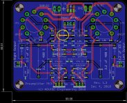
Correct, there is an error with the Gerbers. The input power trace makes no connection on the MK3 Preamplifier board.
E_fortier and I found out many months after the boards were made 🙄
E_fortier and I found out many months after the boards were made 🙄
Last edited:
Thanks for the suggestions. Do I understand from it that the answer to my original question is negative. The question was if +12Vdc would be sufficient to power the Mosfet drivers well enough, if not optimally. What would be optimal?
I have not yet purchased the specified relay due to concerns about its voltage rating, which several had mentioned. Has anyone discovered a part with sufficient switching voltage rating that would fit the PS PCB?
About the relay, you can isolate the contacts by removing R14 and R16 and also the resistor shunting the contacts R15. Then you can put a jumper from the input side of R14 to the output side of R16 . Now you have the contacts isolated and could put the relay in the primary side of the transformer where it’s 250v 5 amp rating is sufficient. You would need to run an extra pair of wires from the HV board to do this. If you want to put resistance in series with the HV you can still use the choke connections on the PS board to do that. If you are using a choke you normally would not put series resistance in the circuit.
I have not checked but I think +12volts will likely do the job. The way the board is set up stock it takes the unregulated supply for the +12v regulator and uses that for the + bias voltage. So you could use that and if you have no issue with noise then you are good. I am just building the EL84 version with a power supply board. I am thinking of putting at least 1 board on the test bench and checking it before I assemble everything. If I do that I will see if 12v will drive the grids to 0volts. My KT88 version uses +22 regulated for the +bias.

- Home
- Amplifiers
- Tubes / Valves
- EL34 Baby Huey Amplifier