Thank you! That seems to help a lot.Rinman,
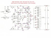
I think that removing R27 wasn't a good idea. That left the feedback floating and may be why you measured a gradual rise in voltage. I believe that what you needed to do here in addition to removing R27 was to short across C7 or C9 which will give you a 1k ohm path to ground via R26 on the feedback side. You should also short the input RCA to ground. This will hold both sides of the
input LTP close to 0V.
I would also leave the output stage rail fuses out during this testing.
Most of the input stage voltages now measure nearly identical on both sides, including 11.8 voltage on base of Q6 & Q10. However there is still something very strange happening at or between Q10 and Q11--this is where the readings diverge dramatically.
I've shown voltage readings in red for the "bad" side, and in blue for the working side. I have not removed any resistors on the working side.
Thanks again!
Ron
Attachments
It is very hot to touch. So it's not open. Low current but high dV.Looks like Q10 doesn't draw any current.
Did you look for replacements?
Figge
I replaced it again just to make sure, but I am getting approximately the same readings as before. Here is my understanding: Q10 will maintain a constant current E to C for a given current E to B, but if something is drawing large current downstream, there will be large resistance E to B, to keep the current constant. So high temperature and low current. This points to a problem downstream, no?
Did you change/check Q11?
With Bob Cordell’s DH-220C design, we put in a jumper block so that we can test the front end without the output stage. How to do that in this design I am not sure due to the topology. In the old Hafler designs you do a small mod to make a mid point in the driver that can be used as your feedback point.
P1,R30 junction would be the mid point to use but I am not sure how you would isolate the OPS. The gates need to be connected to keep the mosfets off they can not be left to float.
All it takes is one faulty mosfet, for troubleshooting purposes all you need is one pair installed
Thinking �� Pull the fuses, lift R32, open connection between R30,31 and gate deive to R38-41, feed from P1,R30 junction to “C”
Post a few pics of that pcb to look at
Last edited:
Did you change/check Q11?
With Bob Cordell’s DH-220C design, we put in a jumper block so that we can test the front end without the output stage. How to do that in this design I am not sure due to the topology. In the old Hafler designs you do a small mod to make a mid point in the driver that can be used as your feedback point.
P1,R30 junction would be the mid point to use but I am not sure how you would isolate the OPS. The gates need to be connected to keep the mosfets off they can not be left to float.
All it takes is one faulty mosfet, for troubleshooting purposes all you need is one pair installed
Thinking �� Pull the fuses, lift R32, open connection between R30,31 and gate drive to R38-41, feed from P1,R30 junction to “C”
Post a few pics of that pcb to look at
I had replaced Q8, Q9, Q10 and Q11 already, but I'm certainly willing to change out Q11 again if it's the possible problem. I guess I'm happy that the IPS seems to be working OK, as those transistors would be more difficult to replace since they are no longer available and in any case would need to be matched. But I still need to know what the problem is in order to fix it. And if I ever get that far I hope this amp sounds amazing.Did you change/check Q11?
With Bob Cordell’s DH-220C design, we put in a jumper block so that we can test the front end without the output stage. How to do that in this design I am not sure due to the topology. In the old Hafler designs you do a small mod to make a mid point in the driver that can be used as your feedback point.
OK, I will work on this more tomorrow. Or I may simply switch out a bunch of FET's to see if it makes a difference. Thanks for the input.
Thank you! That seems to help a lot.
Most of the input stage voltages now measure nearly identical on both sides, including 11.8 voltage on base of Q6 & Q10. However there is still something very strange happening at or between Q10 and Q11--this is where the readings diverge dramatically.
I've shown voltage readings in red for the "bad" side, and in blue for the working side. I have not removed any resistors on the working side.
Thanks again!
Ron
Your image with voltage readings is a great help.
As others are pointing out, You still have current flowing in from the base of Q10/Q11 based on your readings the voltage is higher on the base side of R20/21. I know you replaced Q10/Q11 however this symptom says that either you have the wrong transistor in the Q10/Q11 location, or the device is bad (did you buy them from a reputable source?). Or you have the proper transistor in the proper location but you rotated them 180 degrees from their proper orientation so instead of EBC you have CBE.
In addition to verifying the correct devices are in the right locations I would follow the traces and make sure that the emitter of Q10 is attached to the collector of Q9.
How easy is it to remove those mosfets? Maybe remove one set at a time, maybe you will get lucky
Thinking you might have a bad p-ch mosfet, try removing one Q16-19 at a time
I agree with above, could be a device is installed incorrectly, verify that first before dealing with the mosfets
Thinking you might have a bad p-ch mosfet, try removing one Q16-19 at a time
I agree with above, could be a device is installed incorrectly, verify that first before dealing with the mosfets
Last edited:
The Transnova principle has an inverting input stage and an inverting outputstage.
The Hafler DH-220 is a complete, different but traditional design. You cannot bypass the outputstage bij connecting the output of the drivers to the feedbackloop with the transnova design. It will blow up to pieces before you can say the word oscillation.
The Hafler DH-220 is a complete, different but traditional design. You cannot bypass the outputstage bij connecting the output of the drivers to the feedbackloop with the transnova design. It will blow up to pieces before you can say the word oscillation.
Oops, This is where we should be able to delete our posts, to correct ourselves and not provide incorrect advise. But thanks for correcting me, hopefully the op did not act on my bad advise.
So much for my troubleshooting advise and circuit analysis. Let’s design a circuit that is a PITA to troubleshoot, well done Jim Strickland, where are you now, when we need your advise 🙂
So much for my troubleshooting advise and circuit analysis. Let’s design a circuit that is a PITA to troubleshoot, well done Jim Strickland, where are you now, when we need your advise 🙂
Last edited:
The voltage is higher on the base side of R20, but it is more negative on the base side of R21. This seems to agree with the expected current flow. The NPN (Q11) should have current flow (positive to negative) from the base to the emitter. Am I totally missing something here?Your image with voltage readings is a great help.
As others are pointing out, You still have current flowing in from the base of Q10/Q11 based on your readings the voltage is higher on the base side of R20/21. I know you replaced Q10/Q11 however this symptom says that either you have the wrong transistor in the Q10/Q11 location, or the device is bad (did you buy them from a reputable source?). Or you have the proper transistor in the proper location but you rotated them 180 degrees from their proper orientation so instead of EBC you have CBE.
In addition to verifying the correct devices are in the right locations I would follow the traces and make sure that the emitter of Q10 is attached to the collector of Q9.
Last edited:
I think I must have made a mistake on that reading.Q11b-c is reverse biased, so no current will flow through it
I just replaced Q11 again, (using a socket), and it seems to have changed some of the voltages, but not in a dramatic way that fixes the problem. In a bit I will post a new set of measurements.
I think the measures I posted around Q11 may have been taken at a different time, thus there could have been some warm-up effect or something. Either that or I just made a mistake (entirely possible).
I'm letting it warm up while I have a cup of coffee.
Ron
It looks like I've taken a few steps backwards--The "good" side is no longer good. When I first added the new transistor at Q11 I measured some voltages that were way off. E.g. the +24 on the "good" side had become +12. I then noticed a burning smell. I unplugged the amp, looked for obvious shorts and such, and then plugged it in again. Same result, so I unplugged it again and changed out Q11 with one from a different bag. Both bags were sourced from Digi-Key last week; they have slightly different pin geometry, but the same pin-out. I double/triple checked that it was inserted properly. In any case when I added the different Q11 the voltages went back to normal, but R28 on the good side had turned black, and there is a huge drop across it that wasn't there before--it measures around 11 volts instead of 21 as before. When I tried to measure voltage on the base of Q9 it was fluctuating between ~20 and 11 volts at a frequency of about 1 Hz. Really weird. I had done nothing to this side of the circuit. It seems like I have an entirely new problem😱. I will switch out Q8, 9, 10 and 11 on the formerly "good" side, and take some more measurements.I think I must have made a mistake on that reading.
I just replaced Q11 again, (using a socket), and it seems to have changed some of the voltages, but not in a dramatic way that fixes the problem. In a bit I will post a new set of measurements.
I think the measures I posted around Q11 may have been taken at a different time, thus there could have been some warm-up effect or something. Either that or I just made a mistake (entirely possible).
I'm letting it warm up while I have a cup of coffee.
Ron
Ron
I replaced Q8-11 and R28 and the left side is working again.It looks like I've taken a few steps backwards--The "good" side is no longer good. When I first added the new transistor at Q11 I measured some voltages that were way off. E.g. the +24 on the "good" side had become +12. I then noticed a burning smell. I unplugged the amp, looked for obvious shorts and such, and then plugged it in again. Same result, so I unplugged it again and changed out Q11 with one from a different bag. Both bags were sourced from Digi-Key last week; they have slightly different pin geometry, but the same pin-out. I double/triple checked that it was inserted properly. In any case when I added the different Q11 the voltages went back to normal, but R28 on the good side had turned black, and there is a huge drop across it that wasn't there before--it measures around 11 volts instead of 21 as before. When I tried to measure voltage on the base of Q9 it was fluctuating between ~20 and 11 volts at a frequency of about 1 Hz. Really weird. I had done nothing to this side of the circuit. It seems like I have an entirely new problem😱. I will switch out Q8, 9, 10 and 11 on the formerly "good" side, and take some more measurements.
Ron
I still have the same basic issue with the right side. On the right side I've replaced Q8 and Q11 again, as well as all the diodes, but no change in the behavior. I re-measured voltages on the troubled (Right) side after the amp had time to warm up, so I'm posting these numbers with the same numbers I measured earlier on the Left (good) side.
Attachments
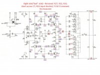
I think that if you connect R27 back then currents will even out.
The voltage flips over fast if currents are unbalanced.
Now there are no reference on feedback input.
Figge
The voltage flips over fast if currents are unbalanced.
Now there are no reference on feedback input.
Figge
I am looking at it this way -
That offset 9V is only possible to come from the C point, between c16 and c19.
That means capacities are not even, can be old (time to recap??)
So, try to connect dummy load and than measure, can happen it will be ok after second or two.
The only question is 18V on q2 drain, where we expect cca 12V.
But in that condition where the whole circuit is out of range is hard to say, and can be wrong measure too.
I would try dummy load first.
A couple of the resistors I removed had broken leads by the time I got them off the PCB, so I have ordered new ones that will arrive Wednesday. I will continue once they arrive. I am replacing electrolytic caps in the meantime.I think that if you connect R27 back then currents will even out.
The voltage flips over fast if currents are unbalanced.
Now there are no reference on feedback input.
Figge
So I'm thinking at this point it may indeed turn out to be an issue with the OPS FETs. If so, I will replace them with Exicon. The data sheets seem very close and the Exicon have a good reputation for sound.
Thanks. I will try dummy load. I had replaced the big caps for a while (with taller ones) but the symptoms were still the same. I put the old ones back so I could install the cover between sessions. All the smaller electrolytic caps are being replaced.I am looking at it this way -
That offset 9V is only possible to come from the C point, between c16 and c19.
That means capacities are not even, can be old (time to recap??)
So, try to connect dummy load and than measure, can happen it will be ok after second or two.
The only question is 18V on q2 drain, where we expect cca 12V.
But in that condition where the whole circuit is out of range is hard to say, and can be wrong measure too.
I would try dummy load first.
Ron
- Home
- Amplifiers
- Solid State
- Hafler Transnova 9300