Can you be more specific, I don’t understand this.If I wanted to turn the amp on, I needed to install the power cord just before turning on, otherwise the fuse was burned.
Hans
Okay, there is power cord always connected from the wall to the amp. Right? When I wanted to switch the amp on I started burning the fuse more and more often during the switch on. Then I noticed that if I disconnect the power cord to the amp for a few seconds and put it back and immediately after that switch on the amp it worked. (Amp switched on without burning the fuse).
When the switch on works right there is about one second delay between when pressing the switch on button and when the amp starts(you can hear the clicking) some kind of delay circuit(maybe you can find it from the schema). When I had this burning fuse issue there were basically no delay at all between pressing the switch on button and amp start.
Now when I have been repairing the amp I have not seen this behavior. And to be clear all this was before I started repairing the amp. I hope this is clear.
Hans,
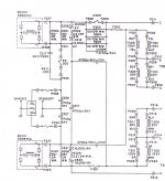
I have question from the schematic; Since I have four wires from main board to the OL-2 board, WH.1, WH.5, WH.2, WH.4, are those respectively +DRIVE, -DRIVE, +MASTER EMITTER and -MASTER EMITTER in the OL-2 board? It is not very clear. Then there is still Io TERMAL +VCC and to OPTO COUPLER.
I think +VCC is clear and to OPTO COUPLER(this I already disconnected) but what is the Io THERMAL? there is thermal sensors in the heatsinks of the mainboard but no connection to OL-2 board ???
I understand what causes the power cord problem and I will also answer your OL-2 questions.
Will come back to you later this morning with details.
Hans
Will come back to you later this morning with details.
Hans
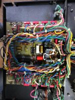
I cannot switch on the amp anymore without the lamps in the VCC unregs. Left channel keeps burning the fuse. Last time just before burning the fuse there was a bit of smoke coming from the front module(picture attached), but I could not locate it. I think problem is somewhere there😀
The PCB is clearly warmed in the area of C329-D313 and the components next to those. Components seems no signs of warming. (front module, next to the right channel opto-coupler).
The PCB is clearly warmed in the area of C329-D313 and the components next to those. Components seems no signs of warming. (front module, next to the right channel opto-coupler).
Attachments
Here I will go into the sometimes problematic power on sequence.
With the rather huge caps in the power supply, 4 * 36.000 uF, an enormous amount of current would flow when powering on just in one go.
That's why precautions are taken for a power on slowing down as follows:
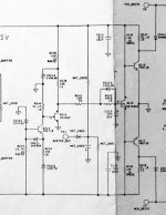
When you press switch SW300, 3 resistors resp. R303 to R305 of 10 Ohm each, are still in the mains line in series with the transformers, see image below.
So the purpose of these resistors is to limit the turn on current to an acceptable value.
Once the power is coming up, the second image below explains the next step.
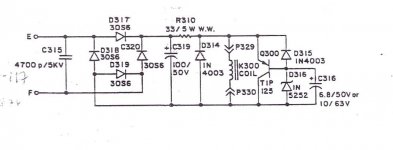
Through E and F from the primary of the transformer, this circuit will turn the 20 Volt Ac into DC on C319. Through R310 Relay K300 will now be energised and switch on.
Q300 parallel to the relay will limit the voltage on the relay to 25 Volt with Zener D316.
So now that Relay K300 is activated, it will close switch K300 in the first image, thereby short circuiting the three 10 Ohm current limit resistors.
You will hear a click and that's the end of the power on sequence.
In the first image you can also see the two rectifiers BR300 and BR301 with a number of components around them.
Their only puropse is to prevent DC current from flowing into the transformers when the Mains supply has a slight offset, because this DC would cause some saturation in the transformers.
Long story, but now you should understand the function of all these components.
To come to your problem that you have to take the power line out and in again to prevent a fuse from blowing, means that K300 does not open after switch off, thereby disabling the slow start sequence.
I can think of a number of reasons why this can happen:
1) A relay has a switch on point, in this case probably some 15-20Volt, but also a switch off point, that is much lower, like 3 to 5 volt.
So when there is still some voltage remaining on this relay, it does not switch off.
That can only mean that either switch SW300 is still conducting some current, or Cap C317 parallel to SW300 is defective and allows just passing enough current to keep Relay K300 closed.
2) Second reason can be that the contacts in Relay K300 keep sticking.
To test this, simply measure the voltage on Relay K300 after power on, see that it is 25Volt DC, switch off the amp and see whether the voltage is dropping to zero volt.
If it does, after having done this a few times you will have to replace the Relay with a new one.
When however some voltage remains on the Relay after swtich off, a voltage that disappears when unplugging the mains cable, you will have to test C317 and switch SW300.
Hans
With the rather huge caps in the power supply, 4 * 36.000 uF, an enormous amount of current would flow when powering on just in one go.
That's why precautions are taken for a power on slowing down as follows:
When you press switch SW300, 3 resistors resp. R303 to R305 of 10 Ohm each, are still in the mains line in series with the transformers, see image below.
So the purpose of these resistors is to limit the turn on current to an acceptable value.
Once the power is coming up, the second image below explains the next step.
Through E and F from the primary of the transformer, this circuit will turn the 20 Volt Ac into DC on C319. Through R310 Relay K300 will now be energised and switch on.
Q300 parallel to the relay will limit the voltage on the relay to 25 Volt with Zener D316.
So now that Relay K300 is activated, it will close switch K300 in the first image, thereby short circuiting the three 10 Ohm current limit resistors.
You will hear a click and that's the end of the power on sequence.
In the first image you can also see the two rectifiers BR300 and BR301 with a number of components around them.
Their only puropse is to prevent DC current from flowing into the transformers when the Mains supply has a slight offset, because this DC would cause some saturation in the transformers.
Long story, but now you should understand the function of all these components.
To come to your problem that you have to take the power line out and in again to prevent a fuse from blowing, means that K300 does not open after switch off, thereby disabling the slow start sequence.
I can think of a number of reasons why this can happen:
1) A relay has a switch on point, in this case probably some 15-20Volt, but also a switch off point, that is much lower, like 3 to 5 volt.
So when there is still some voltage remaining on this relay, it does not switch off.
That can only mean that either switch SW300 is still conducting some current, or Cap C317 parallel to SW300 is defective and allows just passing enough current to keep Relay K300 closed.
2) Second reason can be that the contacts in Relay K300 keep sticking.
To test this, simply measure the voltage on Relay K300 after power on, see that it is 25Volt DC, switch off the amp and see whether the voltage is dropping to zero volt.
If it does, after having done this a few times you will have to replace the Relay with a new one.
When however some voltage remains on the Relay after swtich off, a voltage that disappears when unplugging the mains cable, you will have to test C317 and switch SW300.
Hans
Attachments
I cannot switch on the amp anymore without the lamps in the VCC unregs. Left channel keeps burning the fuse. Last time just before burning the fuse there was a bit of smoke coming from the front module(picture attached), but I could not locate it. I think problem is somewhere there😀
The PCB is clearly warmed in the area of C329-D313 and the components next to those. Components seems no signs of warming. (front module, next to the right channel opto-coupler).
Again we were writing answers simultaneously 😀 😀
As I said before, there are no separate fuses for the Right or the Left channel.
The fuses are in the two mains lines powering both amps at the same time.
You mention that you cannot switch on the amp without the lamps.
Does that mean that with the lamps you can still power on ?
Hans
I cannot switch on the amp anymore without the lamps in the VCC unregs. Left channel keeps burning the fuse. Last time just before burning the fuse there was a bit of smoke coming from the front module(picture attached), but I could not locate it. I think problem is somewhere there😀
The PCB is clearly warmed in the area of C329-D313 and the components next to those. Components seems no signs of warming. (front module, next to the right channel opto-coupler).
I cannot see in your circuit diagram where P340 that powers D313 and C329 is going to, could you try to find out.
Hans
Yes WH.1 and WH.5 are +/- Drive and WH.2 and WH.4 are +/- Master Emitter.Hans,
I have question from the schematic; Since I have four wires from main board to the OL-2 board, WH.1, WH.5, WH.2, WH.4, are those respectively +DRIVE, -DRIVE, +MASTER EMITTER and -MASTER EMITTER in the OL-2 board? It is not very clear. Then there is still Io TERMAL +VCC and to OPTO COUPLER.
I think +VCC is clear and to OPTO COUPLER(this I already disconnected) but what is the Io THERMAL? there is thermal sensors in the heatsinks of the mainboard but no connection to OL-2 board ???
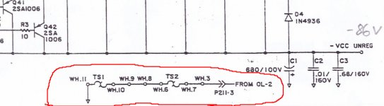
"Io Thermal" goes to the two thermal switches that are on the circuit diagram in your posting #2.
See below, two thermal switches TS1 and TS2 going to OL-2.
If one of both opens because of too much heat, it will activate the signal "Opto Coupler" causing to switch off the Amp through Relay SW300 in your power on switch.
Hans
Attachments
I cannot see in your circuit diagram where P340 that powers D313 and C329 is going to, could you try to find out.
Hans
I could not find it either, but I measured 12V in the line if it helps...
So I can still power up the amp with the lamps, but there is almost 0V in the VCC unregs.
I could not find it either, but I measured 12V in the line if it helps...
So I can still power up the amp with the lamps, but there is almost 0V in the VCC unregs.
12 volt is fine, now I know where it comes from.
O.k. You can power up with the lamps.
And the 0V in the Vcc unreg is on the amp side of the lamp, is that what you mean, the other side of the lamp is +/- 86 Volt, right ?
We have a number of problems all happening at the same time, so let’s go back one step on the primary side to check everything there.
But first tell me what you meant with 0V on the Vcc unreg.
Hans
Before going back to the Right Channel Amp, we first have to check with a few simple tests if everyting on the mains side is still O.K.
1) Without power on, check the resistance between the chassis of the Amp and the gnd output of both speaker outputs terminals. This should be 10 Ohm in both cases.
Between the two speaker gnd terminals you should measure 20 Ohm.
Disconnect the Vcc unregs on BOTH amps, and connect a single 40Watt lamp on each side between the +/-86 Volt.
When switching on, both lamps should burn, and switch it off again.
The lamps are used to discharge the large 36.000uF caps after switching off, that’s why you need them.
2) Now put your Voltmeter on D314, the diode that protects Relay K300.
Switch the amp on and measure the voltage on D314.
Now switch off the amp, and see what the voltage is doing, is it going back to zero ?
When it’s back to zero, repeat this process a few times.
When it’s not going back to zero, pull out the mains power cord and see what happens.
3) With the Amp switched off, measure the resistance over R303, this should be 3.3 Ohm.
4) Still with the amp switched off, measure R300, this should be 34 Ohm.
5) Do the same on R307, this should also be 34 Ohm.
6) When you unplug BR300 on one side, P327 or P328, see with your multimeter whether the diodes in both directions are o.k.
7) Do the same with BR301. Unplug either P337 or P325 and measure the diodes .
This will tell how the state of the mains side components is.
When done, reinstall Vcc unreg to the left amp and place both lamps in the Vcc unreg lines of the right Amp.
Hans
Correct Hans, 0V is on the the amp side.
That's O.k., nothing wrong with that.
Hans
OK. First two steps:
1. Resistance between Right gnd channel and chassis = 12.6 ohm
Resistance between Left gnd channel and chassis = 10.7 ohm
Between grounds = 20 ohms
It was surprisingly difficult to measure these because sometimes it was showing no connection, sometimes hundreds of megaohms, but in the end I got these numbers. Not sure why.
2. This is interesting. During off there is always 230VAC in D314. When switching on it becames DC. Beginning voltage was around 10VDC and then slowly towards 0V. If I switch the the amp on multiple times it can go also to negative like -20VDC and then slowly towards 0V. After switching off it becames very quickly again 230VAC.
Point 1) is okOK. First two steps:
1. Resistance between Right gnd channel and chassis = 12.6 ohm
Resistance between Left gnd channel and chassis = 10.7 ohm
Between grounds = 20 ohms
It was surprisingly difficult to measure these because sometimes it was showing no connection, sometimes hundreds of megaohms, but in the end I got these numbers. Not sure why.
2. This is interesting. During off there is always 230VAC in D314. When switching on it becames DC. Beginning voltage was around 10VDC and then slowly towards 0V. If I switch the the amp on multiple times it can go also to negative like -20VDC and then slowly towards 0V. After switching off it becames very quickly again 230VAC.
Point 2) is completely weird.
You should measure on both sides of D314, not with respect to gnd. Is that what you do ?
Are you sure you have D314 ?
What resistance do you measure over D314.
Should be 75 Ohm max.
Hans
Sorry, I measured respect to ground.
When I measure over the D314 the resistance is 4.8kohm, and I am pretty sure because it is difficult place and I checked it carefully. During off there is 0V and when the amp is on there is 0.8V. And because it is difficult place it is hard to say what is happening just after switching.
When I measure over the D314 the resistance is 4.8kohm, and I am pretty sure because it is difficult place and I checked it carefully. During off there is 0V and when the amp is on there is 0.8V. And because it is difficult place it is hard to say what is happening just after switching.
Sorry, I measured respect to ground.
When I measure over the D314 the resistance is 4.8kohm, and I am pretty sure because it is difficult place and I checked it carefully. During off there is 0V and when the amp is on there is 0.8V. And because it is difficult place it is hard to say what is happening just after switching.
I think you are measuring D315 Instead of D314.
You should measure 25volt when on and 0volt when off.
4.8k is also way off.
Hans
- Home
- Amplifiers
- Solid State
- Mark Levinson No23 repair help