Dear all,
based on this Francois G's post:
https://www.diyaudio.com/forums/tubes-valves/72536-el84-amp-baby-huey-post6132583.html
and on these gingertube's suggestions:
https://www.diyaudio.com/forums/tubes-valves/326920-el34-baby-huey-amplifier-post6144401.html
I would like to open a thread for a group design for a more powerful amp that can be used for Hi-Fi or as a bass amplification.
The Hi-Fi version will have standard screen supply, while the bass amp version could implement the Mesa Boogie "DynaWatt" trick to let the screen supply sag a bit during transitories. I've used it with EL84s and I liked it.
I attach here a first sketch of the amp with 6550s with 600V on plates and 300V dedicated UL taps that will supply the PI too.
Only one bias&driver is sketched, but there will be one for each PA tube.
I've shown that the power supply for the drivers must be approximately ±3 times the bias voltage of the PA tubes, but I don't know exactly how much to expect in this configuration. Will the PI swing what is needed?
Raa should be 4k2 for each pair, so 2k1 in this specific case.
I would like to have your feedback on this, and then how a cheap and powerful tube like the GU50 could be implemented, being on paper not the best tube for this purpose (see this gingertube's post to know why: https://www.diyaudio.com/forums/tubes-valves/72536-el84-amp-baby-huey-post6132342.html )
Thank you all in advance,
Regards
Attachments
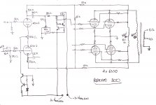
I forgot to mention that I left deliberately g3 unconnected, because I would like to ask if there could be some benefit in some positive reference, even if we are under UL configuration.
I'm referring to this thread:
a better pentode for less!
I will update the schematic as we go on with the discussion.
Thank you,
Regards
Roberto
I'm referring to this thread:
a better pentode for less!
I will update the schematic as we go on with the discussion.
Thank you,
Regards
Roberto
This is the Mesa Boogie's patent I'm referring to for the DynaWatt:
US4713624A - Power amplifier with modified dynamic response
- Google Patents
See the images on the patent to better understand.
US4713624A - Power amplifier with modified dynamic response
- Google Patents
In the preferred embodiment, which is only a seventeen output watt amplifier, resistor 49 has a value of 5600 ohms. This value allows the voltage which supplies the output screen grids 43, 44 as well as the driver circuitry of V3 and V4 to drop by as much as 50 volts or 20 percent. In the seventeen watt amplifier, the size of the capacitor 50 is a relatively large 30 mf and discharges over a period of approximately 50 to 500 milliseconds depending on the amplitude and duration of saturation in the plate circuit of V1 and V2.
After the storage resevoir capacitor 50 has drained down to the lowered incoming voltage supplied by resistor 49, the power sensitivity of the combined amplifier is significantly reduced and the output tubes V1 and V2 are unable to conduct the full resources of the high voltage power supply 32. Soft clipping distortion with smooth, fluid attack conditions result.
When an amplifier of twice the power was built in accordance with the principles of the present invention, the values preferred by the guitarist panel were consistent with the increase in screen current demand: 2800 ohms and 60 microfarads. In a conventional "unmodified" amplifier, there would clearly be no need for 60 mfd for the screen supply filter.
See the images on the patent to better understand.
This will be an interesting thread to follow. Best wishes with the development.
Keep in mind Marc’s previous work in this direction, it parallels you circuit topology closely. (Marc created the BHEL34/84 PCB, based on gingertube’s circuit design.) His goal was to develop the “Ultimate” BH design and called it the TENA, using quad KT88s per channel. TENA = The Emperor’s New Amplifier. He published the schematic and even did a PCB for it, but please note that this is probably a preliminary design that to my knowledge had never been prototyped. Read about it here in post #439
EL34 Baby Huey Amplifier
Notice in the schematic that he proposed following the initial ECC83 pair with ECC82 to achieve greater drive capability. Perhaps this last pair could even be a more power powerful tube, such as ECC99, or a Russian 6N6.
Personally I’m very interested in a good design for a GU50 amplifier for a future project. Since I’m more interested in fidelity than power, a two-tube PP will provide huge power for my needs.
Last edited:
Merci Francois,
I've seen this schematic:
https://www.diyaudio.com/forums/att...r-schema-quad-el34-tena-autobias-reversed-pdf
I have to say that. if possible, I would like to avoid to have gain stages inbetween the PI and the final mosfet drivers to the PA. But PI's clean swing could not be enough.
and the output transformer with cathode feedback:
TTG-CFB2000PP - Tube output CFB transformer [2kOhm] Cathode Feedback Push-pull - Shop Toroidy.pl
That in the SUPREME finish with side windings will cost around 128 euros.
But I don't understand why it is rated for only 80 W as it should give way more.
The problem with that transformer is that it is planned for UL taps taken from the plate winding, not enabling to have two different voltages from plate and screens. On top of that, UL taps are not at 43% without the cathode feedback (it becomes 43% summing UL with CFB being 33+10%).
I will scan that site for other possible commercial solutions. Even if you will need less power, you can just implement two tubes instead of four from the final design.
I would like to implement with easy tubes before, then go to GU50 (I'm interested too on this, as I draw a schematic years ago based on these threads (I hope it's not a problem to link other forums, if it is I will remove the links):
GU50 in a bass or guitar amp?
Bass Power Amp with GU50
I've seen this schematic:
https://www.diyaudio.com/forums/att...r-schema-quad-el34-tena-autobias-reversed-pdf
I have to say that. if possible, I would like to avoid to have gain stages inbetween the PI and the final mosfet drivers to the PA. But PI's clean swing could not be enough.
and the output transformer with cathode feedback:
TTG-CFB2000PP - Tube output CFB transformer [2kOhm] Cathode Feedback Push-pull - Shop Toroidy.pl
Technical data
Intended for Push-Pull CFB
Core type Toroidal
Ultralinear tap 33%
CFB Windings 10% Ra
Nominal Power 80W
Nominal anode current 300mA
Frequency bandwidth (-3dB) 16 Hz - 91 kHz
Secondary Impedance 4 and 8 Ω
Primary Impedance 2 kΩ
Turns Ratio (Np:Ns) 22,36:1 (4Ω) , 15,81:1 (8Ω)
Primary Inductance Lp 580 H
Primary Leakage Inductance Lsp 4,21 mH
Total Primary DC Resistance 65Ω
Effective Primary Capacitance 1,9 nF
Dimensions (standard) 115 mm (OD) x 65 mm (h), weight: 2,8 kg
Dimensions EXPO 120 mm (OD) x 80 mm (h), weight: 4,5 kg
That in the SUPREME finish with side windings will cost around 128 euros.
But I don't understand why it is rated for only 80 W as it should give way more.
The problem with that transformer is that it is planned for UL taps taken from the plate winding, not enabling to have two different voltages from plate and screens. On top of that, UL taps are not at 43% without the cathode feedback (it becomes 43% summing UL with CFB being 33+10%).
I will scan that site for other possible commercial solutions. Even if you will need less power, you can just implement two tubes instead of four from the final design.
I would like to implement with easy tubes before, then go to GU50 (I'm interested too on this, as I draw a schematic years ago based on these threads (I hope it's not a problem to link other forums, if it is I will remove the links):
GU50 in a bass or guitar amp?
Bass Power Amp with GU50
.....
That in the SUPREME finish with side windings will cost around 128 euros.
But I don't understand why it is rated for only 80 W as it should give way more.
<snip>
The problem with that transformer is that it is planned for UL taps taken from the plate winding, not enabling to have two different voltages from plate and screens. On top of that, UL taps are not at 43% without the cathode feedback (it becomes 43% summing UL with CFB being 33+10%).
I believe Toroidy uses the same toroid core for all their larger output transformers, and vary the windings according to the specific need. So, the 80 watts output is probably the max they get with that core.
Toroidy winds custom transformers upon order, so one could possibly get a transformer wound that have separate screen coils. I have not custom ordered from them before, but had seen satisfied customers report who felt the custom work was performed at reasonable cost.
Do you consider it a problem that Marc’s transformers are not 43% UL, but 33% UL + 10% CFB? Why?
It is not a problem per se, but if the project is not supposed to use CFB, then the UL will be not optimal for the power tubes. Well, then I've seen many debates about the best percentages for different tubes, and some seems to need lower values, so it could fit even better than 43%.
Interestingly I sent Toroidy a query last week regarding a custom transformer with a tertiary winding for the screen, for an 807 PP amp with 600v plates and 300v screens. Tomasz investigated for me, but said there was not enough room for the winding.
Thank you OldHector,
what would have been the specs of your transformer?
Any chance to fit this project?
Am I right that 80 Wrms at 19 Hz, if we talk about the core, should be around 200 Wrms at 40 Hz?
what would have been the specs of your transformer?
Any chance to fit this project?
Am I right that 80 Wrms at 19 Hz, if we talk about the core, should be around 200 Wrms at 40 Hz?
Baby Huey Tena-ish combo
Thanks Francois for directing me to this thread.
I did a basic copy and paste design of the Baby Huey EL34, Marc's Tena amplifier and a drawing of audioamp.eu auto bias circuit. I have no business designing an amplifier but I learn most by by doing so with DonPetru's help we came up with the BH100 schematic.
A PPP EL34 with auto bias. I had some boards made and am ready to do some testing, probably this week. If someone is interested in testing the idea I'll send you a pair of boards.
Take Care,
Evan
Attachments
Here is the mail trail ...
Dear Richard.
Sorry but for now it looks like it won’t fits on the core.
Best Regards / Serdecznie pozdrawiam,
Tomasz Lachowski
------------------------------------------------------------------
TOROIDY.PL Transformatory L. Lachowski Sp. k.
Kolonia Koplany 1E
16-061 Juchnowiec Kościelny
tel: +48 85 733 77 73
fax: +48 85 733 77 73
www.toroidy.pl
info@toroidy.pl
From: Richard
Sent: Tuesday, March 31, 2020 12:18 PM
To: Toroidy-INFO
Subject: Re: Screen winding
Hi Tomasz,
Thanks for the reply, and sorry I was slow getting back to you! Hope all is as well as can be expected over there.
I am creating an amplifier for 807 tubes, and am hoping to have 600v on the plates and 300v on the screens. I've researched some circuit ideas, and ultralinear is possible, but because the screen cannot take the high plate voltages, there would have to be a seperate screen winding. That would be a bit like a CFB winding, but 40% instead of 10%, as is usual with CFB. There was a description of such a transformer in my original mail.
It is just a plan for now, so please do not prioritise the request too high!
Best wishes,
Richard
On Monday, March 16, 2020, 10:35:13 AM GMT+1, Toroidy-INFO <info@toroidy.pl> wrote:
Hi.
In my opinion it won’t be a problem to use standard transformer.
In some circuits EL34 tube can works with even higher plate and screen voltages. Insulation withstanding in our transformers in >4kV.
Best Regards / Serdecznie pozdrawiam,
Tomasz Lachowski
------------------------------------------------------------------
TOROIDY.PL Transformatory L. Lachowski Sp. k.
Kolonia Koplany 1E
16-061 Juchnowiec Kościelny
tel: +48 85 733 77 73
fax: +48 85 733 77 73
www.toroidy.pl
info@toroidy.pl
From: Richard
Sent: Monday, March 16, 2020 10:22 AM
To: info@toroidy.pl
Subject: Screen winding
Hi!
I am looking at building an ultralinear, push pull amplifier for 807. The anode to anode load is 6.6kohm, but the problem with the standard UL transformer is the max screen volt rating of the 807. Ideally I would put around 500vdc on the anode, and 250vdc on the screen.
The principal is described here:
Modern High-end Valve Amplifiers
Modern High-end Valve Amplifiers
Explains the whys and wherefores of toroidal output transformers at various technical levels, starting with elem...
Is this something you could do? I presume it is a bit like a CFB tertiary winding?
Best regards,
Richard
Last edited:
Thank you Evan,I learn most by by doing so with DonPetru's help we came up with the BH100 schematic.
may I ask you something?
- R1&R2: there's alot more NFB than the original amp, may I ask you why? Also considering that R13 is quite high.
- R3&R4: is there a reason why they are so low? Old standards for triodes was to have grid stopper like 8/gm. This would mean like 4k7 (when new) to 10k (considering some ageing of the tube) on a 12ax7. So, around a cutoff at 100 kHz in the worst case.
- R38&R39: are there to prevent the wiper of the trimmer to loose connection and so the ground reference for the two triodes, as a safety feature?
- What is the swing that the PI can give to the PA?
Thank you very much and sorry for the multiple questions.
Cheers
Roberto
Thank you Richard,
I will ask him what are the limits for the windings, in order to understand what can be done and what not, and give some guidelines on how to develop the amp with a reasonable price for the transformers in a 100 (down to 20 something Hz) and 200 Wrms (down to 40 something Hz) versions, based on what I see from their site.
If someone has other reasonably prices choices for the trafos, please post.
Thanks!
Roberto
Attachments
OldHector,
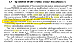
That looks like something Menno van der Veen wrote. He might be a source of a suitable transformer too, but nominally goes up to “merely” 100W output.
See his website:
Specialist: VDV-2100-CFB-SSCR-PPS
That looks like something Menno van der Veen wrote. He might be a source of a suitable transformer too, but nominally goes up to “merely” 100W output.
See his website:
Specialist: VDV-2100-CFB-SSCR-PPS
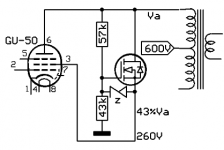
Lower Vg2 UL without extra winding.
Just an idea.
Mona
Interesting. Am I correct that in this arrangement the screen current would have some contribution to output power? Is that why is it better than RC voltage burning screen supplies for “ordinary” tetrode operation. Plus lower impedance?
I have been looking for a good voltage reducing circuit for the purpose of using output tubes at higher plate voltage without a complicated, high-heat producing arrangement, such as 807 outputs with 600v plates and 350V screens. I remember Bruce Rozenblit of Transcendent Sound in one of his designs used long string of low value zeners between the screen and plate (with cap bypass) to accomplish this.
Last edited:
Resistor or mosfet, the voltage difference is allways dissipated in the voltage dropping element.Interesting. Am I correct that in this arrangement the screen current would have some contribution to output power? Is that why is it better than RC voltage burning screen supplies for “ordinary” tetrode operation. Plus lower impedance?
What I propose gives the same voltage swing on the screen as with UL-tap.
But the current change from the screen adds totally to the anode current, with real UL only partly.
Mona
Hi Mona, I am not sure how to derive values for the components in your diagram, apart from the voltage divider part, but I have at least 3 scenarios where I'd really like to have this solution as part of my toolkit.
For instance, I built an EL86 version of the Tubelab SPP, and the screen voltage was a bit too high, which resulted in redplating. In that case I'd like to peg the screen at 200v, with the plate at around 230v.
Then I have some Loctal tubes 5B/255M, that are similar to an 807, which I want to use in a Quad 2 amplifier. with a socket adaptor In that case I need to peg the screen at around 280-300v with the plate at 340v.
Then the more extreme case is to try some 807's, which is closer to your example.
What are the important parameters, and how robust is a solution like this?
Rgds, Richard
- Home
- Amplifiers
- Tubes / Valves
- Baby Huey enters into puberty: 6550 KT88 possibly GU50?