I have a Quad 405 (12368-9) that I am trying to restore and have been following the Dada electronics instructions. Dada (EJP) has kindly helped me via their forum but I still haven’t solved the problem.
I changed all the capacitors, lowered the sensitivity to 1.5v and changed to OPA604 op amps. I changed power wiring as well. Original caps were bulging and crusted. The power caps leaked fluid when I was de-soldering them. The original ul301 opamps were on sockets but the rest of the components looked original. There are no signs of burning on the boards or resistors. The only thing I am not happy with is that I have used 0.25w 3K resistors for R7 and R8. Plan to replace with 1W versions when things get moving here. The chassis is complete apart from the cover which is removed. The clamp circuit was removed and replaced bipolar caps along with new binding posts. I measure -15 and +16.6V going to the op amp. I haven’t done any more voltage checks. I assume the numbers on the schematic are voltages I need to check. I’m a bit nervous of shorting something by mistake as it is a bit cramped.
Both boards worked but had 0.64V DC on the output (both channels). Playing through an old pair of speakers it sounded great. Interestingly, when I unplugged one board I got 0.32v on the output of the remaining channel. I found that by running a wire from the earth lug to the signal earth on the DIN plug I get close to zero DC on the outputs. That is strange as R2 puts 10ohm between signal and power ground. My Proac 1Sc clones have never sounded so good to me. There is a very slight hum on the left channel but that is probably the cable run which needs tidying up. DIN socket wiring is original (shorted earth pins) and I am using the DIN-RCA cable that came with the amp. I made another with 4 core Belden.
Apart from the grounding issue, R31 gets very hot, both boards. Around 72 degC and seems to stabilise there. I have seen this issue on other threads and Dada even suggests putting a higher wattage R31 on the back of the board. I checked all the resistors, pulled a few and refitted and only changed a couple on one board. Still both boards behave the same.
Hope someone has suggestions.
Thanks,
kffern
Last edited:
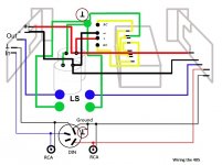
Quad 405 ground wire like this, the input din ground must grounded to the nearby chassis ground otherwise there will be small DC(0.6mv) to the output.
Attachments
Last edited:
The clamp circuit was removed and replaced bipolar caps along with new binding posts.
You mean you put bipolar caps between the amp outputs and speakers.
If like this, please explain why you did this.
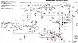
do you try add the 1n cap to the power transistor TR10 between the B-C pins
Is that C19 on the circuit diagram? I changed it to a silver mica to the same pins as original. See attached.
That hot? R30 definitely runs hotter than R31. My non contact thermometer shows a difference when I move it over them and they feel different too.Both R30 and R31 run very hot at the same time is normal
Thanks for your help.
kffern
Attachments
Last edited:
Both R30 and R31 run very hot at the same time is normal
R30 and R31 560R running a current of 44mA and each resistor will be dissipated 1.1w in the circuit.
I plan to order these and change R30 just in case.
RWM0410R560JR15E1 | Vishay RWM 4x10 Series Axial Wirewound Resistor 560mΩ +-5% 3W +-75ppm/degC | RS Components
Would you recommend anything else?
Regards,
kffern
RWM0410R560JR15E1 | Vishay RWM 4x10 Series Axial Wirewound Resistor 560mΩ +-5% 3W +-75ppm/degC | RS Components
Would you recommend anything else?
Regards,
kffern
That hot? R30 definitely runs hotter than R31. My non contact thermometer shows a difference when I move it over them and they feel different too.
these resistors run in series so that they should run in same heat, your case maybe one resistor value drifted or cap C10 leakage.
Attachments
I plan to order these and change R30 just in case.
RWM0410R560JR15E1 | Vishay RWM 4x10 Series Axial Wirewound Resistor 560mΩ +-5% 3W +-75ppm/degC | RS Components
Would you recommend anything else?
Regards,
kffern
This wirewound resistor is good.
when you install the resistor, please lift it 1cm above the PCB for easy heat dissipation.
You mean you put bipolar caps between the amp outputs and speakers.
If like this, please explain why you did this.
The bipolar caps are C17 10uf 50v. The originals looked OK but since I had the board removed to changed the horrible plugs I changed the caps as well.
I have that wiring diagram but as I didn't plan on fitting phono plugs just yet I didn't notice that there wasn't a wire going to earth. Strange as I bought another amp from the same guy and both DIN plugs are the same.
Regards,
kffern
Ok, the bipolar cap is ok.
I think the phono plugs/RCA inputs just for mod, not in the original amp, but the DIN input must be grounded.
these resistors run in series so that they should run in same heat, your case maybe one resistor value drifted or cap C10 leakage.
R31 measures 580ohms. R30 measures 560ohm. Caps are all new.
kffern
The resistors you post (RS stock) are 560mΩ,not 560R!
Your are correct! I'm always careless in small things.
R31 measures 580ohms. R30 measures 560ohm. Caps are all new.
kffern
Your amp seems normal, maybe you change these two resistors to the same type and their temp will be the same.
Thanks everyone for your help. I had the correct resistors in the basket.
Lets see how long it is before they will ship the resistors.
Regards,
kffern
Lets see how long it is before they will ship the resistors.
Regards,
kffern
Ok, the bipolar cap is ok.
I think the phono plugs/RCA inputs just for mod, not in the original amp, but the DIN input must be grounded.
The DIN input must not be grounded. It must be connected to the PCB via the shield, from whence it is grounded to chassis via the 10R ground-lift resistor R2. Same for RCA sockets if fitted: they must be insulated from chassis ground.
- Home
- Amplifiers
- Solid State
- Quad 405, R31 overheating