Greetings
I reflowed all of the joints on that board and replaced the fried resistor.
I took resistance measurements across the pins of the 2SJ74 and 2SK170 on both the working channel and on the potentially damaged channel and I'm sorry to say that they were very different.
On the working side: top pin or bottom pin to middle of 2SJ74: 52k ohms. Top pin to bottom pin: 40 ohms.
(It looked more or less the same for 2SK170)
On the not working side: top pin to middle pin 21 ohms. bottom pin to top pin and top to bottom pin: starts at 0ohm and rises rapidly up through 10 to 100+ ohms.
So I probably have fried JFETs, right?
I need to buy a new matched quad? Or can I just get a matched pair for the one broken channel?
Thank you very much.. Let me know if I should start a new thread instead of continuing on this one.
-Jesse
Greetings
I reflowed all of the joints on that board and replaced the fried resistor.
I took resistance measurements across the pins of the 2SJ74 and 2SK170 on both the working channel and on the potentially damaged channel and I'm sorry to say that they were very different.
On the working side: top pin or bottom pin to middle of 2SJ74: 52k ohms. Top pin to bottom pin: 40 ohms.
(It looked more or less the same for 2SK170)
On the not working side: top pin to middle pin 21 ohms. bottom pin to top pin and top to bottom pin: starts at 0ohm and rises rapidly up through 10 to 100+ ohms.
So I probably have fried JFETs, right?
I need to buy a new matched quad? Or can I just get a matched pair for the one broken channel?
Thank you very much.. Let me know if I should start a new thread instead of continuing on this one.
-Jesse
You only need to match jfets that are in parallel with one another.
I should just buy a new matched quad from the diyaudiostore? and replace both of them on both channels?
Thanks
Thanks
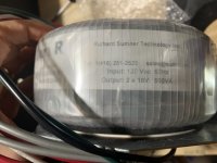
My transformer only has 2 primary leads.
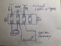
Can someone please advise on the correct wiring for 120V with the 2 CL-60's and and safety cap?
My initial thought is that everything remains the same as the illustrated build guide, except that I connect the leads on the 2 outer terminals.
Can someone please advise on the correct wiring for 120V with the 2 CL-60's and and safety cap?
My initial thought is that everything remains the same as the illustrated build guide, except that I connect the leads on the 2 outer terminals.
Yes it is 120V. I purchased it from SumR.
Is the attached sketch correct?
Secondly, I ordered the same PEM as the diyAudio store, but am confused as to why there are 2 fuses. Does this mean that I should use two, 2.5A fuses, or a different value?
Is the attached sketch correct?
Secondly, I ordered the same PEM as the diyAudio store, but am confused as to why there are 2 fuses. Does this mean that I should use two, 2.5A fuses, or a different value?
Attachments
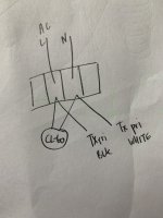
There are 2 fuses in that IEC block...
One fuse could be 2.5A slow blow - make sure this one goes on phase
The other could be 5A slow blow - make sure that this one goes on neutral.
If there's a problem, the 2.5A will blow first (that's the theory...), hence, the primary will not be floating at 120V AC 🙂 🙂
One fuse could be 2.5A slow blow - make sure this one goes on phase
The other could be 5A slow blow - make sure that this one goes on neutral.
If there's a problem, the 2.5A will blow first (that's the theory...), hence, the primary will not be floating at 120V AC 🙂 🙂
There are 2 fuses in that IEC block...
One fuse could be 2.5A slow blow - make sure this one goes on phase
The other could be 5A slow blow - make sure that this one goes on neutral.
If there's a problem, the 2.5A will blow first (that's the theory...), hence, the primary will not be floating at 120V AC 🙂 🙂
The PEM on my F5 has 2 fuses, and I put 2.5A in both. Never knew why it had fuses on both hot and neutral.
OK, I won't 🙂
I'm not in a rush... will only do anything once I get a clear answer on how-to
I suggest that you take it slowly !!!
Do exactly what you have planned to do: Do not rush, get a clear answer here on forums, make sure that it makes sense to you, and then do one thing at the time.
Follow this...
Thank you so much... this makes much more sense!
My new JFETs come tomorrow. I'm worried that whatever fried the first ones are going to fry this batch. My plan is to get everything connected and then use my DMM to compare resistances on the known good side to the repaired side before applying any power. See if I can learn to use the diode tester function too.
Why did I buy new JFETs? Couldn't it be one of the other transistors that died?
Anyway... Thanks as always..
-Jesse
Why did I buy new JFETs? Couldn't it be one of the other transistors that died?
Anyway... Thanks as always..
-Jesse
Use an antistatic wrist strap when handling FET's; in particular the JFETs.
Diode tester... get a BJT (any BJT -> the ZTX's will do nicely) and try the diode tester -> it will start making sense🙂
You can not test the JFETs with a diode tester, unfortunately...
Diode tester... get a BJT (any BJT -> the ZTX's will do nicely) and try the diode tester -> it will start making sense🙂
You can not test the JFETs with a diode tester, unfortunately...
Wooot!
Ayeeeee!
I'm shaking from waiting for the smoke to come out...
It didn't come out!
I believe we have an AMP!
Thank you for all the help!
After playing with my multimeter resistance setting, the old JFETs, and the new JFETs, I determined that the 2SJ74 was behaving different than it's new counterpart... So that is what was fried. How it got fried.. I do not know..
-Jesse
Attachments


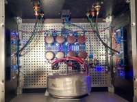
Another F5v3 is born... thanks for the support from all the folks in this forum.
This amp sounds AMAZING.... couldn't stop listening first time I tried it.
Nice!!
What is the ideal gain of a preamp before the F5?
My DAC output is on the low side, 1.3V.
Playing a 0dbFS 1khz .wav file, I measure 8.3Vrms on the F5, which is ~6x or 15dB which is up to spec of the F5.
Is it correct that the F5 would need 2.35V input signal to reach 25W output to 8ohm?
((2.35V * 6)^2 / 8) = ~25W ?
My DAC output is on the low side, 1.3V.
Playing a 0dbFS 1khz .wav file, I measure 8.3Vrms on the F5, which is ~6x or 15dB which is up to spec of the F5.
Is it correct that the F5 would need 2.35V input signal to reach 25W output to 8ohm?
((2.35V * 6)^2 / 8) = ~25W ?
- Home
- Amplifiers
- Pass Labs
- F5 V3