Just finished building my rotary subwoofer and it works quite well. One problem is however that it generates excessive wind noise which I would like to try to eliminate. I've heard one suggestion that includes building some form of baffle system that will absorb high frequencies manually well passing the very low frequencies that are being generated by the rotary sub .more or less a manual low pass filter. Can anyone share how this would be designed. Thanks
Just finished building my rotary subwoofer and it works quite well. One problem is however that it generates excessive wind noise which I would like to try to eliminate. I've heard one suggestion that includes building some form of baffle system that will absorb high frequencies manually well passing the very low frequencies that are being generated by the rotary sub .more or less a manual low pass filter. Can anyone share how this would be designed. Thanks
You would do well to research air conditioning silencers - your needs are very similar. We had a huge one in the acoustic measurements lab where I used to work which wrapped around the rear and side of the building. We'd only know if it was running if someone opened one of the rev chamber doors and all the office doors would slam shut or wide open!
Key to remember is that you should not have line of sight from the listening area to the fan.
Keep us posted, and good luck.
Air blowed in closed circuit, as it can in a serie 6th order bandpass with a really big passive radiator as output port for high freq filtering. ^^ Would need high power equivalent qts...but theorically awesome.
Last edited:
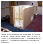
Have you tried building a manifold chamber like Thigpen uses for the TRW-17?One problem is however that it generates excessive wind noise which I would like to try to eliminate.
Attachments
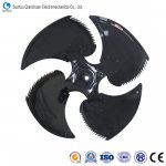
What do the blades of the fan look like? Ideally they should be a symmetrical airfoil. If they are just flat it will generate a lot more turbulence/noise and reduce efficiency.

They look a little bit too thin for a subsonic airfoil, since it looks 3d printed I'd suggest trying fatter blades with feathered /serrated trailing edges.
Last edited:
Thanks for the advice! Can you provide more details regarding your "feathered /serrated trailing edges" suggestion? Any other ideas would be greatly appreciated.
Scott
Scott
You will have harsh aerodynamic spill off from outboard leading edge, unless you place the fan in a ducted assembly (with a carefully controlled tip clearance).
I advise you blend the outboard leading to trailing edge. Think the rounded edges of a desk fan. Where is this blade design from? It is very harsh.
Line of sight means nothing. Acoustics doesn't care. Do not bend the flow if possible!
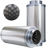
You would be best to create a circular duct silencer. Try this to start:
ID = 1x diameter of source
Length = 1x diameter of source
Lining material = 50mm to 100mm rockwool
I advise you blend the outboard leading to trailing edge. Think the rounded edges of a desk fan. Where is this blade design from? It is very harsh.
Line of sight means nothing. Acoustics doesn't care. Do not bend the flow if possible!
You would be best to create a circular duct silencer. Try this to start:
ID = 1x diameter of source
Length = 1x diameter of source
Lining material = 50mm to 100mm rockwool
Also, is your leading edge significantly higher diameter than the trailing? This will create some major long scale vortices (loud and uncontrollable)
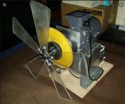
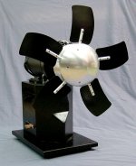
Thanks for the info! LOL the blade design is harsh! I printed the blades using Chris Hudlin's design (see pic). These blades are just a starting point to test the basic concept. I plan to design new blades based on the expertise of people such as yourself. The other pic is that of the only rotary subwoofer that is commercially available. It is made by EMINENT TECHNOLOGY and costs about $20K. What do you think of there blase design?You will have harsh aerodynamic spill off from outboard leading edge, unless you place the fan in a ducted assembly (with a carefully controlled tip clearance).
I advise you blend the outboard leading to trailing edge. Think the rounded edges of a desk fan. Where is this blade design from? It is very harsh.
Line of sight means nothing. Acoustics doesn't care. Do not bend the flow if possible!
You would be best to create a circular duct silencer. Try this to start:
ID = 1x diameter of source
Length = 1x diameter of source
Lining material = 50mm to 100mm rockwool
Regards,
Scott
Attachments
I am not specialised in turbomachinery nor do I know the specific application, but can give basics.
I do not know the reason for the curved edges on the Eminent, The Hudlin design looks a better start point.
Your camber on aerofoil seems extreme for the application. I do not know the stall angle but unless optimised and understood, an aerofoil / other odd shapes will do more harm than good.
How to progress (as I can understand) from your design to Hudlin:
1. Decrease camber significantly to give more 2D cross section
2. Make leading and trailing edge both same length
3. Blend outboard edges of leading and trailing edge
4. 'Sharpen' outboard edge to a thin knife. (Please don't touch on rotation!)
If you model this up and show, I can further assess 🙂
Also, worth mentioning that you could have acoustic issues with heavy blades and flexible shaft.. Lighter blades and stiffer+shorter shaft better.
Reduce infill if possible, and ideally balance system after assembly.
Reduce infill if possible, and ideally balance system after assembly.
I spoke with an industrial engineer who deals with fan noise, they suggested lining the fan shroud with open cell foam (2 in thick) with little to no gap between the blade tips and the foam. With this method you want "flat" tips which conforms to the shroud's inside radius. The foam liner should be rounded on both faces (like a horn/port) and flat inside where the blades pass.
I spoke with an industrial engineer who deals with fan noise, they suggested lining the fan shroud with open cell foam (2 in thick) with little to no gap between the blade tips and the foam. With this method you want "flat" tips which conforms to the shroud's inside radius. The foam liner should be rounded on both faces (like a horn/port) and flat inside where the blades pass.
This would work well, with a small modification.
Open cell foam as an acoustic attenuator is very difficult to get working below 500Hz. This recommendation is excellent for HVAC systems where they typically deal with blade pass effects down to this region, medium scale turbulence or are able to treat over long lengths to attenuate all noise.
With a rotary you'd want strong attenuation by the 3rd harmonic (120Hz I assume for you), but not at the fundamental. This would warrant a short (<2D length) silencer after the fan with exceptional attenuation in LF, hence a deep fill of rock wool, ideally 100mm.
As mentioned above, you would ideally control tip clearance / leakage, so may be worth using a more reliable material than fluff here! You also risk a snow cannon effect if it strays into the blades...
Re blade design how about a sickle shape with serrated trailing edges? Re fan shroud design how about large version of this S9 -Sound Reducer- Duct Cooling Shroud Nozzle Fan Antminer Bitcoin BITMAIN ASIC | eBay or the pic blow?
Attachments
Jsthomps,Re blade design how about a sickle shape with serrated trailing edges?
While there is always room for incremental improvement in every design, can't think of any reason why that sickle shape fan shape would be an improvement over Thigpen's blade with "nosecone" and the noise reduction plenum he uses, as posted previously in #5.
In the OP, you wrote your rotary subwoofer works "quite well", have you done any measurements of your system to benchmark any improvements that you make?
Other than the fun of DIY, do you have any sound pressure level/frequency goals that you want to achieve that can't be achieved with conventional subwoofers occupying a similar amount of real estate?
Art
Last edited:
Hi Art,Jsthomps,
While there is always room for incremental improvement in every design, can't think of any reason why that sickle shape fan shape would be an improvement over Thigpen's blade with "nosecone" and the noise reduction plenum he uses, as posted previously in #5.
In the OP, you wrote your rotary subwoofer works "quite well", have you done any measurements of your system to benchmark any improvements that you make?
Other than the fun of DIY, do you have any sound pressure level/frequency goals that you want to achieve that can't be achieved with conventional subwoofers occupying a similar amount of real estate?
Art
When I said that it works quite well I meant that it is working properly electromechanically. I can't test its effectiveness until I place it in an infinite baffle. That said I have measured the SPL with the fan spinning at 800 rpm in neutral which is +12Db above the noise floor. Reducing that 12Db through blade design and baffle systems is what I am focusing on. Only a rotary sub woofer can reproduce a significant SPL below 20Hz. No convention sub can do this no matter how big or powerful. This is obvious when I send a 10Hz signal though a convention sub. The cone meanders back an forth pushing little to no air. Even worse at 5Hz. Only a rotary sub can produce +100SPL at those infrasonic frequencies.
Scott
- Home
- Loudspeakers
- Subwoofers
- Rotary subwoofer baffle system