Hi, First time posting here.
I bought a bunch of All American Five radios with the idea of gutting them, essentially just keeping the vintage shell and the chassis. And then building a small 1 or 2 tube amp with bluetooth input. Basically a vintag-y tabletop bluetooth player for gifts. (Yes I realize that it would be cheaper, easier, and probably sound better if I bought a bunch of Chinese class-d amp boards, but my friends all know I build tube guitar amps, and I can't go around giving them all guitar amps!). I don't need more than 170v so I can use an admittedly-inexpensive 120/120 transformer and a solid state rectifier, but then I got thinking....
First of all, I totally get why the AA5 design was a safety disaster, and I get why iso transformers protect the against the situation where the presumed-neutral wire shares a common ground with the circuit (because it may in fact be hot). But...
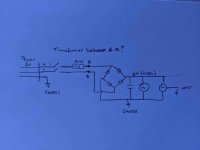
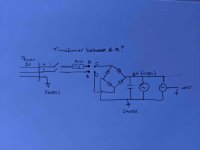
If the picture below represents my design without a transformer, what is the advantage of putting a transformer between A-B? I'm trying to understand the scenario where the transformerless design is less safe. Are there other considerations (noise, etc).
It seems like heresy to ask these questions. I got my head taken off over at a guitar amp forum just for asking, and never got an answer that I could understand. I'm happy to do it "just because" (which was the answer I eventually got), but I really would like to understand.
btw, someone will ask "what about the heaters?. I have no interest in stepping wall voltage down to 6.3v with resistors, zeners, mosfets, or capacitors - too many issues there - so I will get small 120/6.3v transformers for that. I'm just wondering if I can keep my "iron" to one inexpensive transformer.
Thanks. Be nice.
I bought a bunch of All American Five radios with the idea of gutting them, essentially just keeping the vintage shell and the chassis. And then building a small 1 or 2 tube amp with bluetooth input. Basically a vintag-y tabletop bluetooth player for gifts. (Yes I realize that it would be cheaper, easier, and probably sound better if I bought a bunch of Chinese class-d amp boards, but my friends all know I build tube guitar amps, and I can't go around giving them all guitar amps!). I don't need more than 170v so I can use an admittedly-inexpensive 120/120 transformer and a solid state rectifier, but then I got thinking....
First of all, I totally get why the AA5 design was a safety disaster, and I get why iso transformers protect the against the situation where the presumed-neutral wire shares a common ground with the circuit (because it may in fact be hot). But...
If the picture below represents my design without a transformer, what is the advantage of putting a transformer between A-B? I'm trying to understand the scenario where the transformerless design is less safe. Are there other considerations (noise, etc).
It seems like heresy to ask these questions. I got my head taken off over at a guitar amp forum just for asking, and never got an answer that I could understand. I'm happy to do it "just because" (which was the answer I eventually got), but I really would like to understand.
btw, someone will ask "what about the heaters?. I have no interest in stepping wall voltage down to 6.3v with resistors, zeners, mosfets, or capacitors - too many issues there - so I will get small 120/6.3v transformers for that. I'm just wondering if I can keep my "iron" to one inexpensive transformer.
Thanks. Be nice.
Attachments
 As a new member I sincerely hope that you have read the RULES. If not, do so now. This thread will remain open for now to give the membership a chance to explain why this is dangerous.
The audio circuit is earthed (as it must inevitably be) which means current flows from live, through your circuit, to earth. This is forbidden, and will trip your circuit breaker / RCD.
Pan, Thanks. It didn't occur to me that asking the question was in violation of the rules.
Merlin, I'm honored to have you address my ignorance. I love your book. I've read it 4 or 5 times - each time learning more.
So, I'm getting close to understanding this. My question is: why does the same problem not exist on the primary side of the transformer? I had thought the isolation issue was primarily one of a potentially hot chassis, but I'm coming to understand the risk is larger than that.
Wall current should flow from live to neutral, which it does through the transformer primary. You are not allowed to let current flow from live to earth! That only happens when something is faulty, and you have home circuit breakers that sniff out when this happens. Your bridge rectifier would break the rule. (Notice that transformerless vintage appliances only use half-wave rectifiers).
You can get a 'hot' chassis with a transformer, but it's the difference between 'hot' meaning you are accidentally connected to the AC wall supply, and 'hot' meaning you are accidentally connected to the amp's DC power rail. The wall supply is 'trying' to get to earth and can supply many amps. You are earth. The DC power rail, on the other hand, is only trying to return to the transformer, not necessarily through your body. Also, it is much more current limited.
If you need a cheap power supply you could use a low voltage wall-wart or power brick that provides isolation (we all have these lying around from old junk applicances) plus a cheap DC-DC boost converter to create the HT. You can buy them from eBay China. The power brick can supply the heaters too, of course.
Last edited:
be mindful of using a power brick for the heaters etc., they are not always the 'cleanest' of DC and can induce hum and/or unwanted noise.
If you can, check it on a scope to make sure it is 'clean', if not, add some additional caps, but then also make sure the voltage regulator used in the power brick can take additional capacitance!
If you can, check it on a scope to make sure it is 'clean', if not, add some additional caps, but then also make sure the voltage regulator used in the power brick can take additional capacitance!
The wall supply is 'trying' to get to earth and can supply many amps. You are earth.
You're only Earth if you're standing on the HVAC vent in sweat soaked socks late at night. 😱 Ask me how I know! Haha.
This video may have some info on getting cheap iron: YouTube
Basically stringing two 120/6V transformers back to back, grabbing the 6V for heaters before stepping back up to 120V and rectifying. This video also covers getting more than 170V out of the other side, but that's not needed for you.
Regards,
Don
Going back to your drawing, what prevents your circuit current from going hot to ground instead of hot to neutral?
I certainly hope the moderators keep this post up. Safety discussions should not be censored.
I certainly hope the moderators keep this post up. Safety discussions should not be censored.
Thanks guys! And especially Thank You Merlin, for the "long form" answer. I've been waiting for the moment when I can smack my forehead and say "Now I get it!"
One last question: you say line voltage can't come into contact with earth, but aren't the neutral ground and the ground wire connected at the service panel? I thought that electrically they were identical, except that the ground wire was reserved for ground faults.
Frank, that's actually what I meant, I was just too lazy to show both sets of connections. But thanks.
You must use an isolation transformer - Simply for your safety and that of your friends and family.
Without an isolation transformer it is possible to have Live mains voltages on an external connection. I.e the input jack. Remember faults do occur...
In the 'old' days radios without transformers took measures to insulate or isolate any metal parts so you could not touch them. Sometimes not very well either.
If you isolate the mains voltage via a transformer from the active circuit, the earth / ground gives you real protection and if properly designed, you cannot come into contact with the 'hot' mains or 'hot' voltages generated by the transformer secondary.
Plenty to read on the web as to why you need isolating from the mains...
I'm getting closer. (Not to believing you, only to understanding). Here's where I'm still struggling. In an amplifier, we attach the ground/earth wire from the wall voltage to the chassis, which also effectively attaches the neutral wire to the chassis. We also attach the center tap of the transformer secondary to the chassis, as well as our circuit ground(s). So it seems like the circuit is not really isolated at all, except that the voltage risk has been reduced to half the secondary voltage, since the fault will now return to the secondary through the center tap (assuming there is one). So doesn't the grounding scheme in the traditional amplifier design undermine the isolating properties of the transformer?
Yes and yes. Yes in a general sense both neutral and earth are electrically the same. And yes, the ground wire is reserved for faults. Which is precisely why a transformerless supply is forbidden, because you're allowing current that isn't fault current to flow from live to earth. Why? It is inevitable because in normal audio appliances the 'audio circuit ground' is also connected to mains earth as standard, and the user can touch circuit ground during normal handling, which means he can become part of the live circuit. It's different for a double-insulated appliance where the 'circuit ground' is not connected to mains earth and the user cannot touch any part of the operating circuit.One last question: you say line voltage can't come into contact with earth, but aren't the neutral ground and the ground wire connected at the service panel? I thought that electrically they were identical, except that the ground wire was reserved for ground faults.
When you use a transformer, live current can only flow back through the neutral wire, except during a genuine fault. When the user touches circuit ground he is merely touching mains earth; no ordinary current is trying to find it's way to earth through his body.
Last edited:
In Industrial plants I have seen power mains with 3 wire 120V outlets that had a big surprise . . .
The difference at the user end of the power mains Ground and Neutral connections was up to 8VAC.
That is because Neutral current is exactly as large as the Hot current.
Both Neutral and Hot had 8VAC drop at the user end, versus the voltage at the Power Mains Circuit Breaker Panel. These long runs used about a #12 size wire.
But the # 12 gauge ground safety wire Only has leakage currents, not power currents (any thing other than that is Abnormal).
Imagine what happened to the scope probe's # 22 gauge ground clip was connected to the Neutral wire. The scope was grounded through a proper 3 wire power plug and power mains outlet.
The scope probe # 22 gauge ground clip was trying to overcome the 8VAC difference between Neutral wire of # 12 Gauge, and Safety ground wire of #12 Gauge.
The # 22 probe ground clip got smoked!
Neutral and Ground are Not the same (except all the way back to the Power Mains Circuit Breaker).
Never forget that!
Safety First!
"Grounds Are Commonly Misunderstood" - me
Last edited:
You show a fuse inline with active (hot), but not neutral. This way you shouldn't have a situation where only the neutral fuse blows and you have an apparently dead circuit which is still at active potential.
With this proper fusing and an isolation transformer, if active and neutral were accidentally swapped then the transformer would give galvanic isolation. Current wouldn't flow through just one side of the primary to the secondary due to the insulation between them. (Mount the transformer and the fuse close to each other, securely, and near the mains input.)
With this proper fusing and an isolation transformer, if active and neutral were accidentally swapped then the transformer would give galvanic isolation. Current wouldn't flow through just one side of the primary to the secondary due to the insulation between them. (Mount the transformer and the fuse close to each other, securely, and near the mains input.)
I didn't read all the replies in detail to see if this has been said already in another way, but if you look at the top left-hand diode in your schematic it will have its cathode connected to mains live, and its anode connected to mains ground, which is essential the equivalent of mains neutral. In other words that top left-hand diode is connected directly across the mains supply.
That's not the only thing bad about your schematic, of course, but it's a start!
That's not the only thing bad about your schematic, of course, but it's a start!
In an amplifier, we attach the ground/earth wire from the wall voltage to the chassis, which also effectively attaches the neutral wire to the chassis.
Any connection between the protective earth wire and the neutral wire (which an amp connects to via the wall socket), is the regulated domain of the electric utility and is covered by the country electric codes.
The protective earth and the neutral may well be connected at some point in the supply, but that is not for you to 'utilise'. You can't alter that part of the electricity supply, but if you are concerned then call an electrician to confirm your house and internal wiring is acceptable.
The only common way your equipment is allowed to connect a device between Active/neutral and earth is when that device is specified and approved for such a connection, as exampled by EMI filter devices.
It is often illegal in countries to alter mains ac connected appliances without getting the appliance inspected and tested to allow it to then be connected to the supply. This is typically a very regulated domain in many countries, and why purchasing equipment should come with an approved tested sticker or marking, and why people risk their lives when buying second hand equipment or equipment built or modified by diyers or semi-professional sellers if the mains cord hasn't been cut off or a sticker applied stating that the equipment should be tested by a competent person first.
Last edited:
Hi, First time posting here.
btw, someone will ask "what about the heaters?. I have no interest in stepping wall voltage down to 6.3v with resistors, zeners, mosfets, or capacitors - too many issues there - so I will get small 120/6.3v transformers for that. I'm just wondering if I can keep my "iron" to one inexpensive transformer.
Thanks. Be nice.
Use the Antek AS-05T120 transformer. Provides a 120 volt isolated winding AND 6.3 volts for heaters.

If you need a cheap power supply you could use a low voltage wall-wart or power brick that provides isolation (we all have these lying around from old junk applicances) plus a cheap DC-DC boost converter to create the HT. You can buy them from eBay China. The power brick can supply the heaters too, of course.
If you want one of these I'll send you one for the cost of postage. I think they are noisy junk and refuse to use them for anything but testing.
This one, however, is very good. DC-AC Converter 12V to 110V 200V 220V 280V 150W Inverter Boost Board Transformer | eBay

- Home
- Amplifiers
- Tubes / Valves
- Understanding Isolation Transformers